Eureka AIR delivers breakthrough ideas for toughest innovation challenges, trusted by R&D personnel around the world.

Shadowless lighting equipment

A technology for lighting equipment and driving devices, applied in the field of medical equipment, can solve the problems of low adjustment accuracy and troublesome use of shadowless lamps, and achieve the effects of precise control of the spot size, high adjustment accuracy, and continuous adjustment of the spot size.

Pending Publication Date: 2019-11-08
深圳市睿智龙电子科技有限公司
View PDF0 Cites 5 Cited by
  • Summary
  • Abstract
  • Description
  • Claims
  • Application Information

AI Technical Summary

Problems solved by technology

[0003] Shadowless lamps often need to adjust the irradiation position and spot size during use. However, the adjustment of the irradiation position and the spot size of traditional shadowless lamps can only be done manually, which will lead to low adjustment accuracy of the shadowless lamp, and more troublesome to use

Method used


Image

  • Shadowless lighting equipment
  • Shadowless lighting equipment
  • Shadowless lighting equipment

Examples


Embodiment Construction

[0048] In order to facilitate the understanding of the present invention, the present invention will be described more fully below with reference to the associated drawings. Preferred embodiments of the invention are shown in the accompanying drawings. However, the present invention can be embodied in many different forms and is not limited to the embodiments described herein. On the contrary, the purpose of providing these embodiments is to make the disclosure of the present invention more thorough and comprehensive.

[0049] It should be noted that when an element is referred to as being “fixed” to another element, it can be directly on the other element or there can also be an intervening element. When an element is referred to as being "connected to" another element, it can be directly connected to the other element or intervening elements may also be present. In contrast, when an element is referred to as being "directly on" another element, there are no intervening ele...


PUM


Abstract

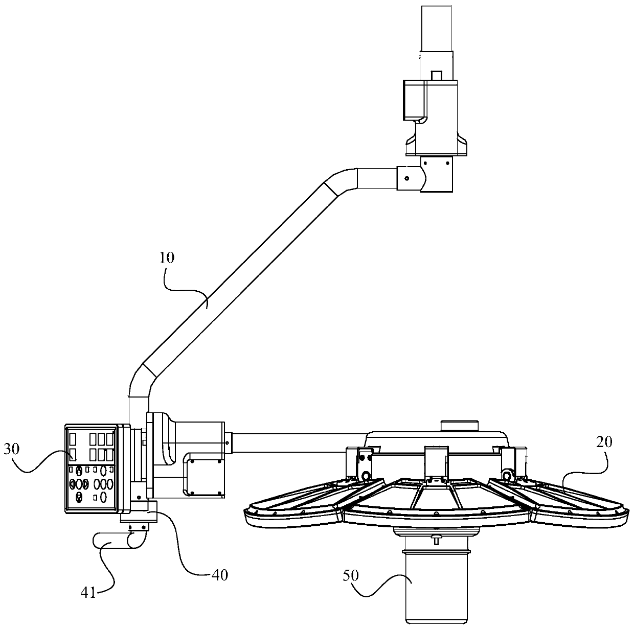
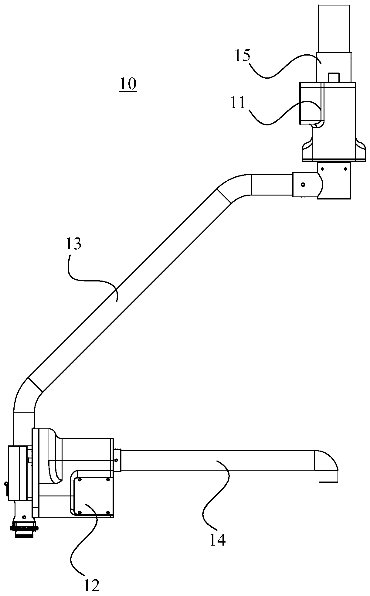
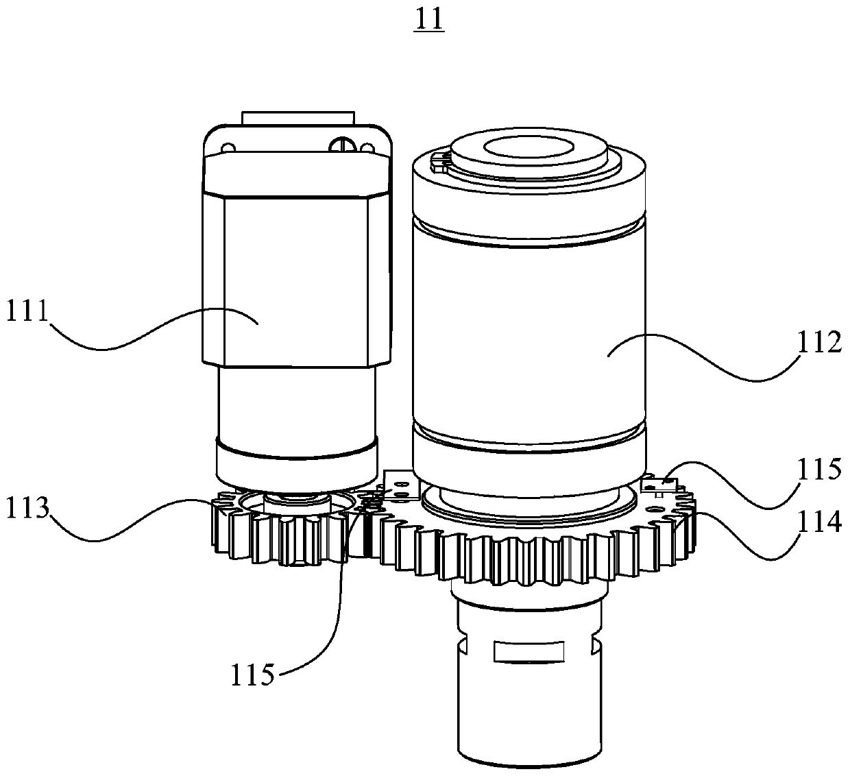
The invention relates to shadowless lighting equipment. The shadowless lighting equipment comprises a cantilever mechanism, a lamp panel mechanism and a controller; the cantilever mechanism comprisesa first driving device, a second driving device, a first cantilever body and a second cantilever body; the second cantilever body is rotatably installed on the first cantilever body; the first drivingdevice is used for driving the first cantilever body to rotate in the vertical direction; the second driving device is used for driving the second cantilever body to perform axis rotation around thesecond cantilever body; the lamp panel mechanism is installed on the second cantilever body; the lamp panel mechanism comprises a third driving device, a first transmission turntable and multiple first lamp bodies; the third driving device is used for driving the first transmission turntable to perform spinning motion; multiple swing components are distributed along the circumferential direction of the first transmission turntable, and connected with the first transmission turntable; each swing component is connected with a first lamp body; and the first transmission turntable can drive the multiple swing components and the first lamp bodies to swing synchronously through spinning rotation. The shadowless lighting equipment in the invention is relatively high in adjustment precision and convenient to use.

Description

technical field [0001] The invention relates to the technical field of medical instruments, in particular to a shadowless lighting device. Background technique [0002] The shadowless lamp is a special equipment that adjusts the angle of the lamp or the angle of the polished reflective surface into a ring light, so as to achieve the shadow or dead angle formed by the convex and concave structures of the irradiation site, and become a picture with uniform brightness, providing illumination for the surgical area. [0003] Shadowless lamps often need to adjust the irradiation position and spot size during use. However, the adjustment of the irradiation position and the spot size of traditional shadowless lamps can only be done manually, which will lead to low adjustment accuracy of the shadowless lamp, and It is more troublesome to use. Contents of the invention [0004] Based on this, it is necessary to provide a shadowless lighting device for the above technical problems. ...

Claims


Application Information

Patent Timeline
Patent Type & Authority Applications(China)
IPC IPC(8): F21S8/00F21V19/02F21V21/15F21V21/28F21V33/00F21W131/205
CPCF21S8/00F21V19/02F21V21/15F21V21/28F21V33/0052F21W2131/205
Inventor 钟晚生
Owner 深圳市睿智龙电子科技有限公司
Why Eureka
Eureka Blog
Learn More