
Projection apparatus and its lens adjusting mechanism

A technology for adjusting mechanisms and projection devices, which is applied in the direction of using projection devices, image reproducers, projection devices, installations, etc., and can solve problems such as inability to adjust at will, lack of compensable tolerances, and inability to perform lens adjustments

Inactive Publication Date: 2006-07-26
QUISDA CORP
View PDF0 Cites 11 Cited by
  • Summary
  • Abstract
  • Description
  • Claims
  • Application Information

AI Technical Summary

Problems solved by technology

In other words, once the lens is fixed, it cannot be adjusted at will, so lens adjustment cannot be performed, and of course there is no ability to compensate for tolerances

Method used


Image

  • Projection apparatus and its lens adjusting mechanism
  • Projection apparatus and its lens adjusting mechanism
  • Projection apparatus and its lens adjusting mechanism

Examples


Embodiment Construction

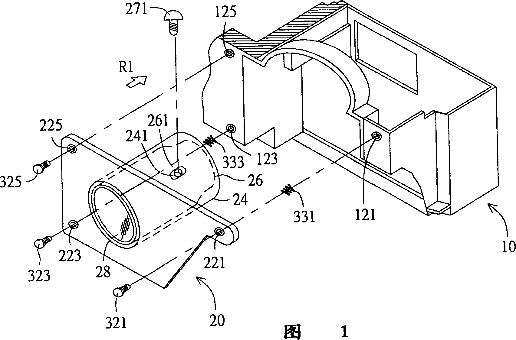
[0043] The present invention proposes a lens adjustment mechanism, which adjusts the lens of the projection device in a simple and efficient manner to compensate for the tolerance of the combination of each optical component, and the adjusted lens can accurately project the image completely on the on the screen. The present invention will be further described in detail with a preferred embodiment below. However, the protection scope of the present invention is not limited to all the elements listed in this embodiment. In addition, unnecessary elements are omitted from the diagrams in order to clearly show the embodiments of the present invention.

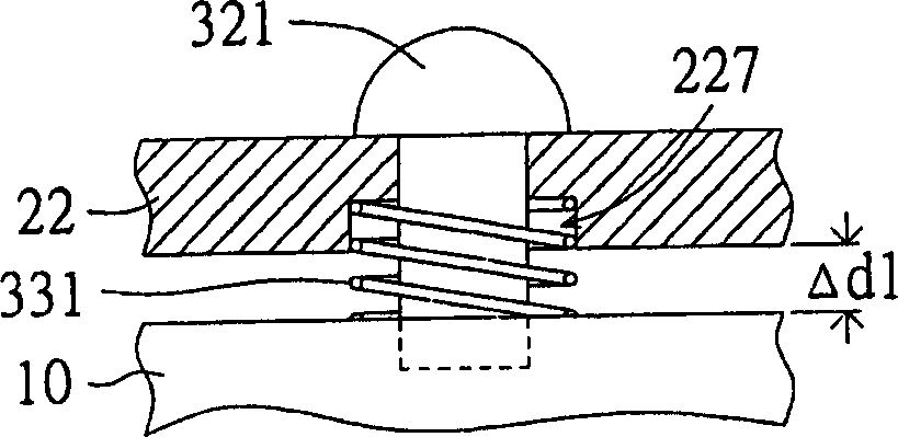
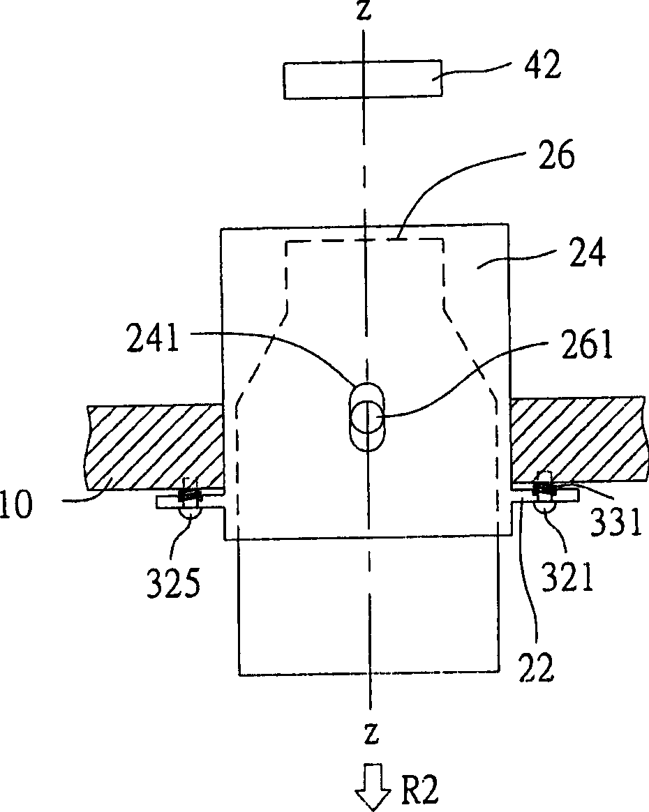
[0044] Referring to FIG. 1 , FIG. 1 is a schematic diagram illustrating the assembly of a lens assembly and a frame of a projection device according to a preferred embodiment of the present invention. In the projection device, a frame 10 is mainly used to set up main components such as a light source, an optical component, an imag...


PUM


Abstract

Disclosed are a projecting device and its lens adjusting mechanism. The lens is placed in a lens tube which is placed in a lens shell body supported by a frame. The adjusting mechanism comprises: a base board, a first positioning component, a second positioning component and a third positioning component. The base board connected with the lens tube is fixed on the lens shell body and mounted on the frame. The first positioning component is placed in a first corner on the base board; the second positioning component is placed in a second corner on the base board; the third positioning component is placed in a third corner on the base board, herein the first and second corners presenting diagonal position on the base board, and at least the first and second positioning components are adjustable to be positioning on the first and second corners. The central axis of the lens and the light axis are parallel or doubling by adjusting the relative position of the first, second and third positioning components.

Description

technical field [0001] The invention relates to a lens adjustment mechanism, and in particular to a lens adjustment mechanism of a projection device. Background technique [0002] With the improvement of Chinese people's requirements for quality of life, the concept of home theater has penetrated into all social strata. The market for home theater projection devices (such as projector rear projection TVs) has also become a battlefield for various projection device manufacturers to compete with each other. For manufacturers, how to manufacture high-quality projection devices that meet consumers' expectations has become an important issue. [0003] The projection device mainly includes a light source, an optical component, an imaging component and a lens component. When the projection device is in operation, the light generated by the light source is projected onto the imaging element through the optical assembly, and then reflected to the lens through the imaging element to ...

Claims


Application Information

Patent Timeline
Patent Type & Authority Applications(China)
IPC IPC(8): G02B7/02G03B21/00H04N5/74H04N9/31
Inventor 林颖芳
Owner QUISDA CORP
Learn More