Motor rotation and swing mechanism

A technology of a swing mechanism and a rotating shaft, which is applied in the direction of electric components, electrical components, electromechanical devices, etc.

Pending Publication Date: 2019-11-08
JULI AUTOMATION EQUIP ZHEJIANG CO LTD
View PDF0 Cites 2 Cited by
  • Summary
  • Abstract
  • Description
  • Claims
  • Application Information

AI Technical Summary

Problems solved by technology

The current motor production equipment and auxiliary equipment cannot achieve the above purpose. Therefore, it is necessary to design a new motor rotation and swing mechanism to meet the needs of motor production.

Method used


Image

  • Motor rotation and swing mechanism
  • Motor rotation and swing mechanism

Examples


Embodiment Construction

[0013] The technical solutions of the present invention will be clearly and completely described below in conjunction with the accompanying drawings. Apparently, the described embodiments are some of the embodiments of the present invention, but not all of them. Based on the embodiments of the present invention, all other embodiments obtained by persons of ordinary skill in the art without making creative efforts belong to the protection scope of the present invention.

[0014] In the description of the present invention, it should be noted that the terms "center", "upper", "lower", "left", "right", "vertical", "horizontal", "inner", "outer" etc. The indicated orientation or positional relationship is based on the orientation or positional relationship shown in the drawings, and is only for the convenience of describing the present invention and simplifying the description, rather than indicating or implying that the referred device or element must have a specific orientation, ...


PUM


Abstract

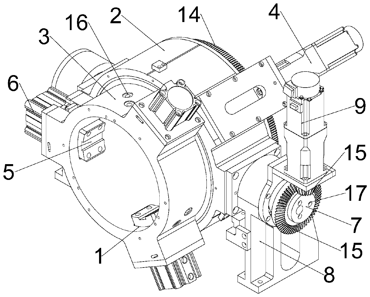
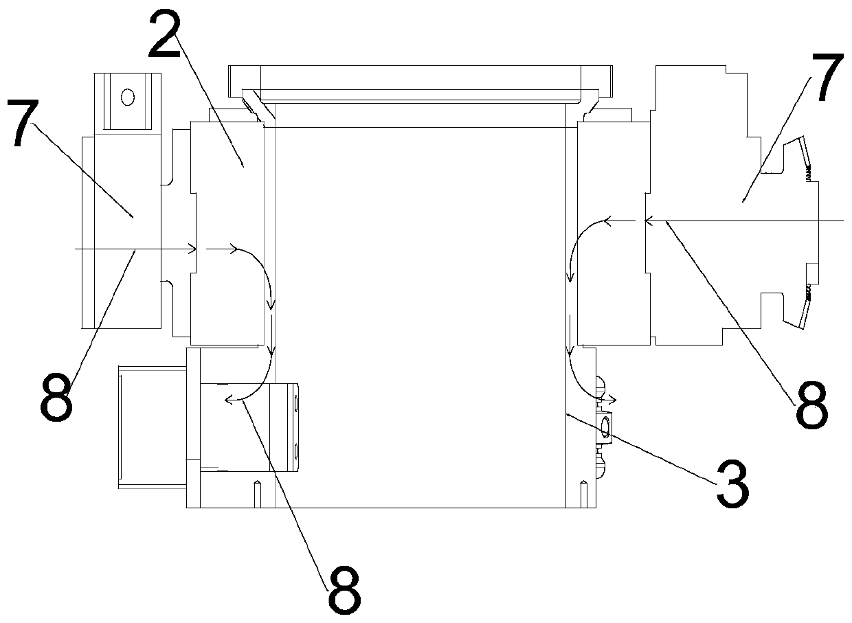
The invention discloses a motor rotation and swing mechanism. The motor rotation and swing mechanism comprises an outer cylinder and an inner cylinder. The inner cylinder rotatably sleeves the outer cylinder. One end of the inner cylinder protrudes out of the outer cylinder and is equipped with a clamping device, and the other end of the inner cylinder protrudes out of the outer cylinder and is connected with a first a motor, the clamping device comprises a plurality of clamping blocks located in the inner cylinder, wherein the clamping block is driven by the cylinder to move towards the central axis of the inner cylinder, and the two sides of the outer cylinder are respectively fixedly connected with horizontally arranged rotating shafts, and the rotating shafts are respectively rotatablyinstalled on a support through bearings, and one of the rotating shafts is driven to rotate by a second motor. The motor rotation and swing mechanism can put the motor in various postures such as horizontal and inclined postures, and can continuously drive the motor to rotate so as to meet the requirements of various postures of the motor in the production process of the motor, and facilitate operation of other devices for the semi-finished motor. By adopting the gear transmission mode, the rotation speed and the inclined angle of the motor can be accurately controlled, and the postures of the motor can be accurately positioned.

Description

technical field [0001] The invention belongs to the technical field of motor production, and in particular relates to a motor rotation and swing mechanism. Background technique [0002] The production process of motors involves many processes. It is often necessary to use auxiliary production equipment such as conveyor belts and manipulators to transport and transfer semi-finished motors. These auxiliary equipments cooperate with other production equipment to greatly improve the production efficiency of motors. The motor stator winding needs to rotate the motor continuously during the paint dripping process, and can swing to form various postures such as horizontal and inclined. The current motor production equipment and auxiliary equipment cannot achieve the above-mentioned purpose. Therefore, it is necessary to design a new motor rotation and swing mechanism to meet the needs of motor production. Contents of the invention [0003] In order to solve the above-mentioned t...

Claims


Application Information

Patent Timeline
Patent Type & Authority Applications(China)
IPC IPC(8): H02K7/10H02K7/116
CPCH02K7/10H02K7/1166
Inventor 章日平张晓军张勇吴应龙余晓雷
Owner JULI AUTOMATION EQUIP ZHEJIANG CO LTD
Why Eureka
Try Eureka