Multi-machine compatible side-mounted clamping and turnover mechanism
A turning mechanism and side-mounted technology, which is applied in the direction of workpiece clamping devices, cleaning methods and appliances, chemical instruments and methods, etc., can solve the problems of affecting the use effect of equipment, complex structure of turning mechanism, and many driving mechanisms, so as to reduce design And the effects of maintenance cost, simplification of clamping and turning mechanism, and design cost reduction
- Summary
- Abstract
- Description
- Claims
- Application Information
AI Technical Summary
Problems solved by technology
Method used
Image

Examples
specific Embodiment approach 1
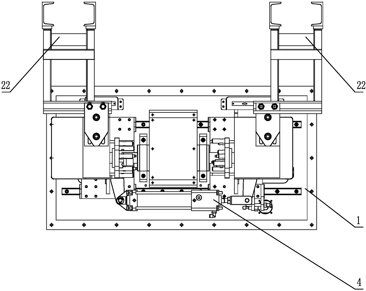
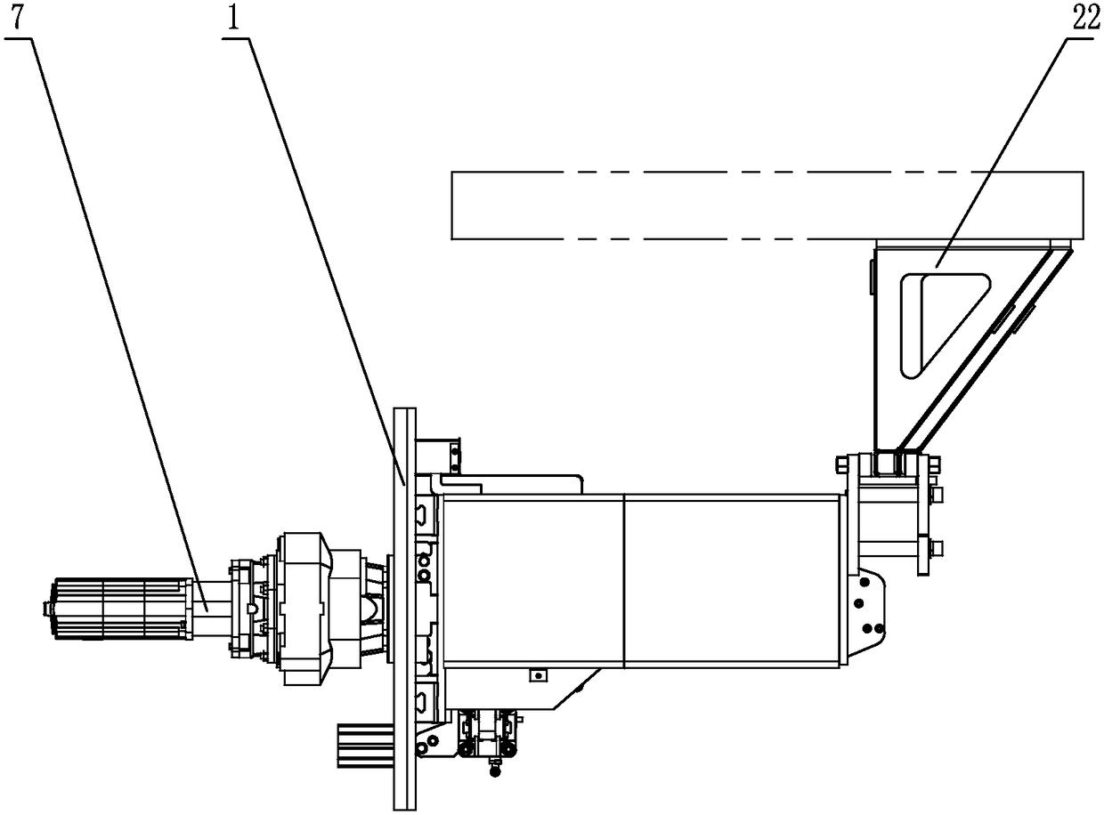
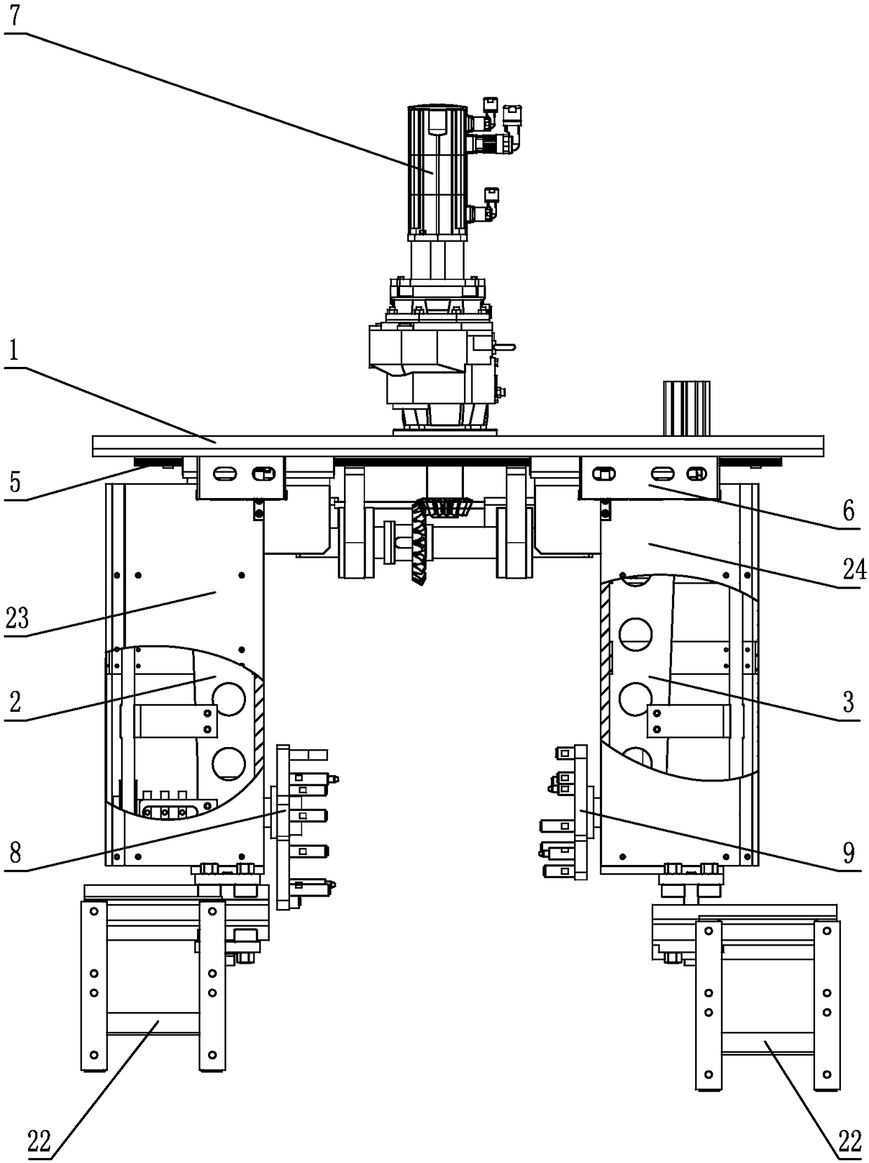
[0019] Specific implementation mode one: combine Figure 1 to Figure 4 Describe this embodiment, a multi-model compatible side-mounted clamping and turning mechanism of this embodiment, which includes a base 1, a left swing arm 2, a right cantilever 3, a clamping drive cylinder 4, a linear guide mechanism 5, and an in-position detection mechanism 6. Servo drive motor 7, left chuck 8, right chuck 9, power transition mechanism and two overturning mechanisms, the base 1 is provided with a linear guide rail mechanism 5, the left swing arm 2 and the right cantilever 3 are respectively located on the base 1 Both sides are slidingly connected with the linear guide mechanism 5, the clamping drive cylinder 4 is installed between the left swing arm 2 and the right cantilever 3, one end of the clamp drive cylinder 4 is fixedly connected with the left swing arm 2, and the other end of the clamp drive cylinder 4 It is fixedly connected with the right cantilever 3, and the base 1 is provide...
specific Embodiment approach 2
[0021] Specific implementation mode two: combination Figure 4 with Figure 5 Describe this embodiment, the power transition mechanism of this embodiment comprises speed reducer 10, small bevel gear 11, fixed shaft 12, fixed bearing housing 13 and large bevel gear 14, and servo drive motor 7 is provided with speed reducer 10, small bevel gear 11 is installed on the shaft end of the reducer 10, the large bevel gear 14 is installed on the fixed shaft 12 and meshed with the small bevel gear 11, the fixed bearing seat 13 is installed on the base 1, and the fixed shaft 12 is connected to the fixed bearing seat 13 in rotation . In this way, the servo drive motor 7 drives the small bevel gear 11 on the speed reducer 10 to rotate in a certain direction, and the small bevel gear 11 drives the fixed shaft 12 to rotate through the large bevel gear 14 . Other compositions and connections are the same as in the first embodiment.
specific Embodiment approach 3
[0022] Specific implementation mode three: combination Figure 6 to Figure 9 Describe this embodiment, each turning mechanism of this embodiment comprises driving shaft 15, driving pulley 16, belt 17, driven shaft 18, driven pulley 19 and tension mechanism, driving shaft 15 and left arm 2 or right The cantilever 3 is rotationally connected, one end of the driving shaft 15 is connected with the fixed shaft 12, the other end of the driving shaft 15 is provided with a driving pulley 16, the driven shaft 18 is rotationally connected with the left arm 2 or the right cantilever 3, and one end of the driven shaft 18 Fixedly connected with left chuck 8 or right chuck 9, the other end of driven shaft 18 is provided with driven pulley 19, and driving pulley 16 is connected with driven pulley 19 by belt 17, and driving pulley 16 is connected with driven pulley. Tension mechanism is provided between belt pulley 19. In this way, the fixed shaft 12 of the power transition mechanism drives ...
PUM
 Abstract
Description
Claims
Application Information
 - R&D
- Intellectual Property
- Life Sciences
- Materials
- Tech Scout
- Unparalleled Data Quality
- Higher Quality Content
- 60% Fewer Hallucinations
Browse by: Latest US Patents, China's latest patents, Technical Efficacy Thesaurus, Application Domain, Technology Topic, Popular Technical Reports.
© 2025 PatSnap. All rights reserved.Legal|Privacy policy|Modern Slavery Act Transparency Statement|Sitemap|About US| Contact US: help@patsnap.com