Visual buried point test method and device

A test method and test result technology, applied in the computer field, can solve the problems of low test efficiency, difficult operation by non-professional technicians, and high professional requirements for testers.

Active Publication Date: 2019-11-12
SUNING CLOUD COMPUTING CO LTD
View PDF5 Cites 8 Cited by
  • Summary
  • Abstract
  • Description
  • Claims
  • Application Information

AI Technical Summary

Problems solved by technology

[0004] Most of the existing buried point detection is a manual test solution. For example, according to the help document process provided by the buried point technology developer, the buried point party checks whether the corresponding data has a report record through the console of th

Method used


Image

  • Visual buried point test method and device
  • Visual buried point test method and device

Examples


Embodiment 1

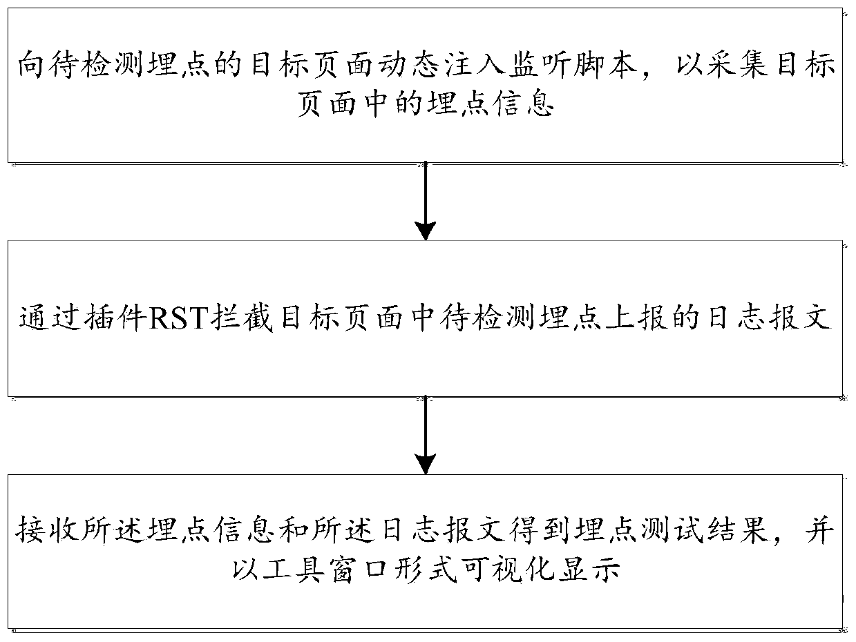
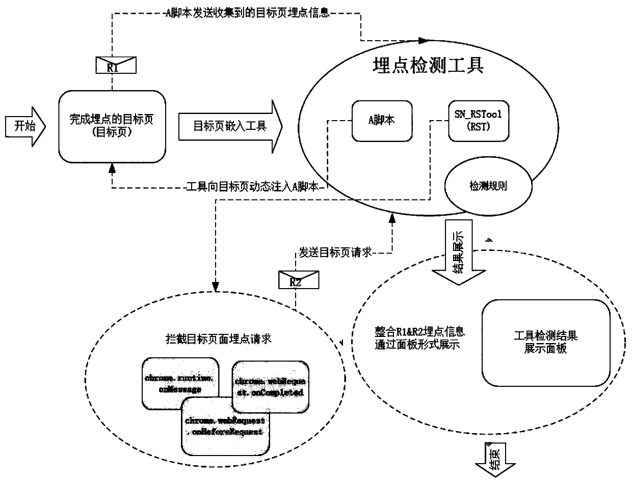
[0043] see figure 1 and figure 2 , this embodiment provides a visual buried point testing method, including:

[0044] Dynamically inject monitoring scripts into the target page of the buried point to be detected to collect the buried point information in the target page; intercept the log message reported by the buried point in the target page through the plug-in RST; receive buried point information and log messages to get buried Point test results are displayed visually in a tool window.

[0045] In the visual buried point testing method provided by this application, first build a tool, and then use the tool to dynamically inject a monitoring script into the target page containing the buried point to be detected to collect the buried point information in the target page, and intercept the pending point in the target page through the plug-in RST Detect the log message reported by the buried point. The buried point information includes the introduction information and locat...

Embodiment 2

[0071] This embodiment provides a visual buried point test device, including:

[0072] The collection module is used to dynamically inject monitoring scripts into the target page of the buried point to be detected, so as to collect the buried point information in the target page;

[0073] The interception module is used to dynamically inject monitoring scripts into the target page of the buried point to be detected, so as to collect the buried point information in the target page;

[0074] The display output module is used to receive the buried point information and the log message to obtain the buried point test result, and visually display it in the form of a tool window.

[0075] Compared with the prior art, the beneficial effect of the visualized buried point test device provided by the embodiment of the present invention is the same as that of the visualized buried point test method provided by the first embodiment above, and will not be repeated here.

Embodiment 3

[0077] This embodiment provides a computer-readable storage medium. A computer program is stored on the computer-readable storage medium. When the computer program is run by a processor, the steps of the above-mentioned indoor positioning method are executed.

[0078] Compared with the prior art, the beneficial effect of the computer-readable storage medium provided by this embodiment is the same as the beneficial effect of the visual buried point testing method provided by the above technical solution, and will not be repeated here.

[0079] Those of ordinary skill in the art can understand that all or part of the steps in the above inventive method can be completed by instructing related hardware through a program. The above program can be stored in a computer-readable storage medium. When the program is executed, it includes: For each step of the method in the above embodiments, the storage medium may be: ROM / RAM, magnetic disk, optical disk, memory card, and the like.


PUM


Abstract

The invention discloses a visual buried point test method and device, relates to the technical field of computers, and aims to realize visualization of buried point test results and improve buried point test efficiency. The method comprises the steps of dynamically injecting a monitoring script into a target page of a to-be-detected burying point to acquire burying point information in the targetpage; intercepting a log message reported by a to-be-detected buried point in the target page through the plug-in RST; and receiving the burying point information and the log message to obtain a burying point test result, and visually displaying the burying point test result in the form of a tool window. The device applies the method in the scheme.

Description

technical field [0001] The invention relates to the field of computer technology, in particular to a method and device for visual buried point testing. Background technique [0002] In order to conduct statistics and analysis of user behavior on the page, the current method usually used is to embed statistical code in the corresponding position of the code of the application or page, that is, to bury it. [0003] By tracking the user's behavior on the corresponding application or page, including clicking, sliding, downloading, browsing, etc.; by making statistics on multiple tracking data, the continuous behavior of the user can be tracked, and the collected data can also be input The established model can be used to obtain the user's operation behavior. By burying points, statistics such as page views, number of unique visitors, IP, page stay time, page operation time, page visits, button clicks, file download times, etc. can also be obtained statistically, and can be used...

Claims


Application Information

Patent Timeline
IPC IPC(8): G06F11/36
CPCG06F11/3688G06F11/3692
Inventor 胡晓王金保李成陶莉孙迁
Owner SUNING CLOUD COMPUTING CO LTD
Why Eureka
Try Eureka