Ink-jet printing device
An inkjet printing device and inkjet printing technology, which are applied in the directions of inking device, power transmission device, printing, etc., can solve the problems of uneven thickness of inkjet printing film layer and low inkjet printing efficiency, and improve inkjet printing. The uniformity of film thickness and the effect of improving the efficiency of inkjet printing
- Summary
- Abstract
- Description
- Claims
- Application Information
AI Technical Summary
Problems solved by technology
Method used
Image

Examples
Embodiment Construction
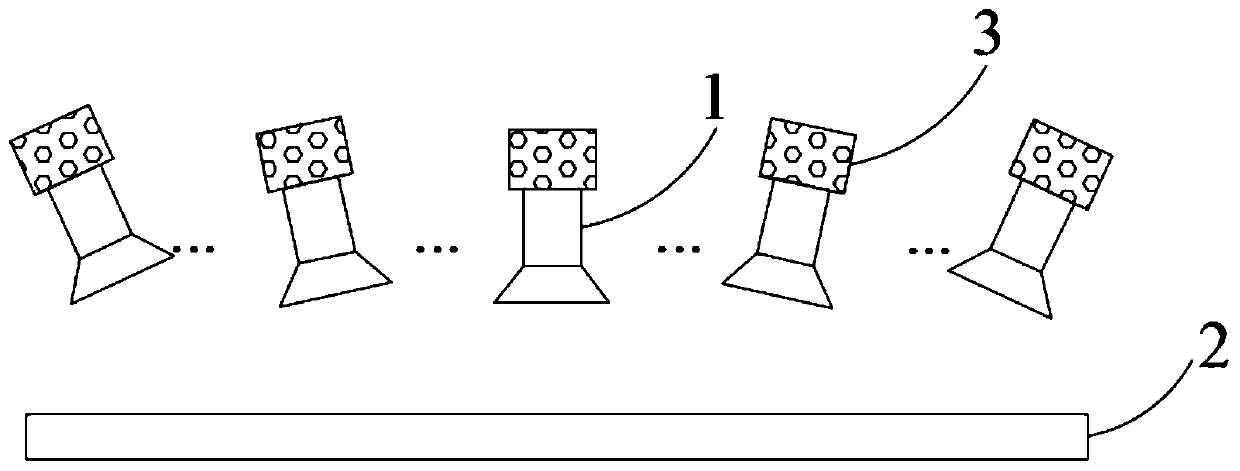
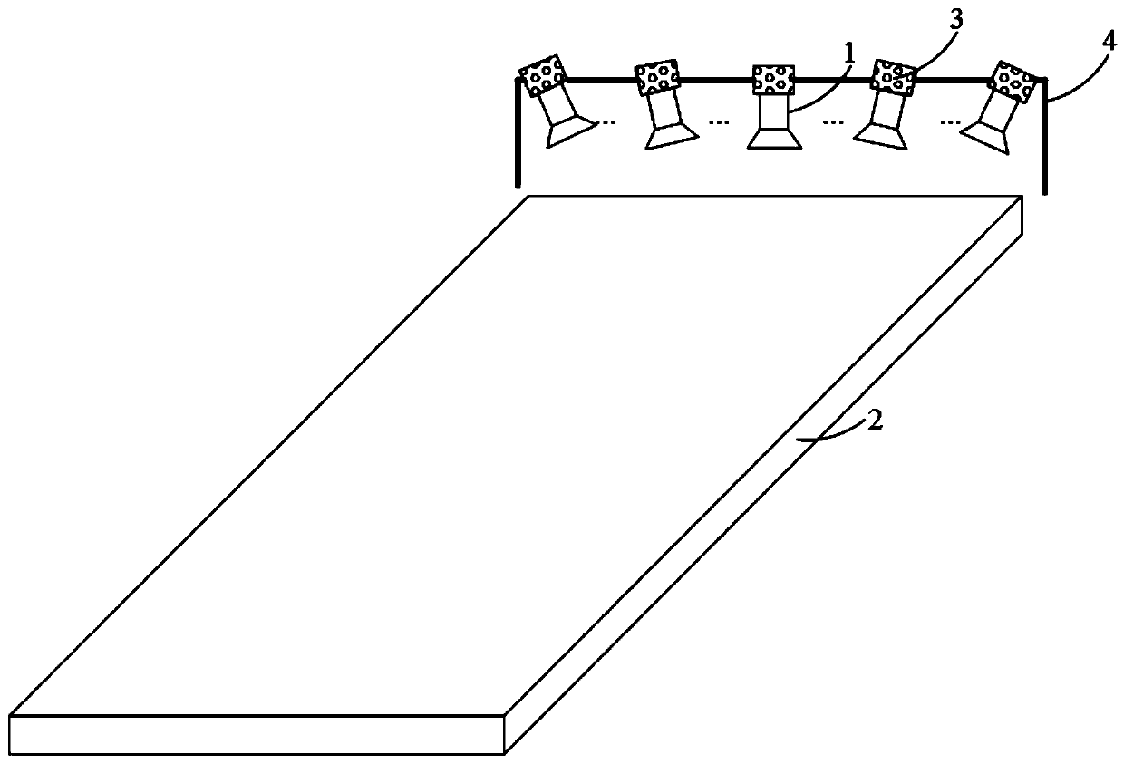
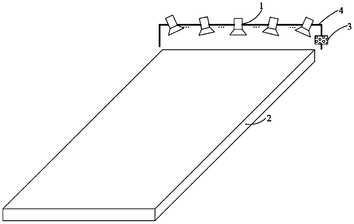
[0021] As mentioned in the background, there are technical problems of low inkjet printing efficiency and non-uniform inkjet printing film thickness in the prior art. The inventor found that the reason for this problem is that due to the limitation of the location and quantity of the nozzles, the ink droplets need to diffuse from the middle area of the substrate to be ink-jetted to the edge area of the substrate to be ink-jetted. Ink droplet diffusion takes time, which affects printing efficiency; the ink droplet diffusion path is uncontrollable, and after film formation, the film thickness at the edge of the substrate to be inkjet is smaller than the film thickness at the starting position of diffusion, and the film thickness is not uniform. In an inkjet process, the larger the inkjet volume of a nozzle, the longer the ink droplet spreads, and the lower the printing efficiency; the more uncontrollable the spread, the more uneven the thickness of the film layer. In additio...
PUM
 Abstract
Description
Claims
Application Information