Eureka AIR delivers breakthrough ideas for toughest innovation challenges, trusted by R&D personnel around the world.

Texture mapping method, device and apparatus based on three-dimensional model

A 3D model and texture mapping technology, applied in the field of computer vision, can solve the problems of texture feature mapping 3D model, poor mapping effect, etc.

Pending Publication Date: 2019-11-19
HANGZHOU HIKVISION DIGITAL TECH
View PDF4 Cites 4 Cited by
  • Summary
  • Abstract
  • Description
  • Claims
  • Application Information

AI Technical Summary

Problems solved by technology

[0003] Applying the above scheme, if the target in the selected texture image is occluded, the texture features of the occluded area cannot be mapped to the 3D model, and the mapping effect is poor

Method used


Image

  • Texture mapping method, device and apparatus based on three-dimensional model
  • Texture mapping method, device and apparatus based on three-dimensional model
  • Texture mapping method, device and apparatus based on three-dimensional model

Examples


Embodiment approach

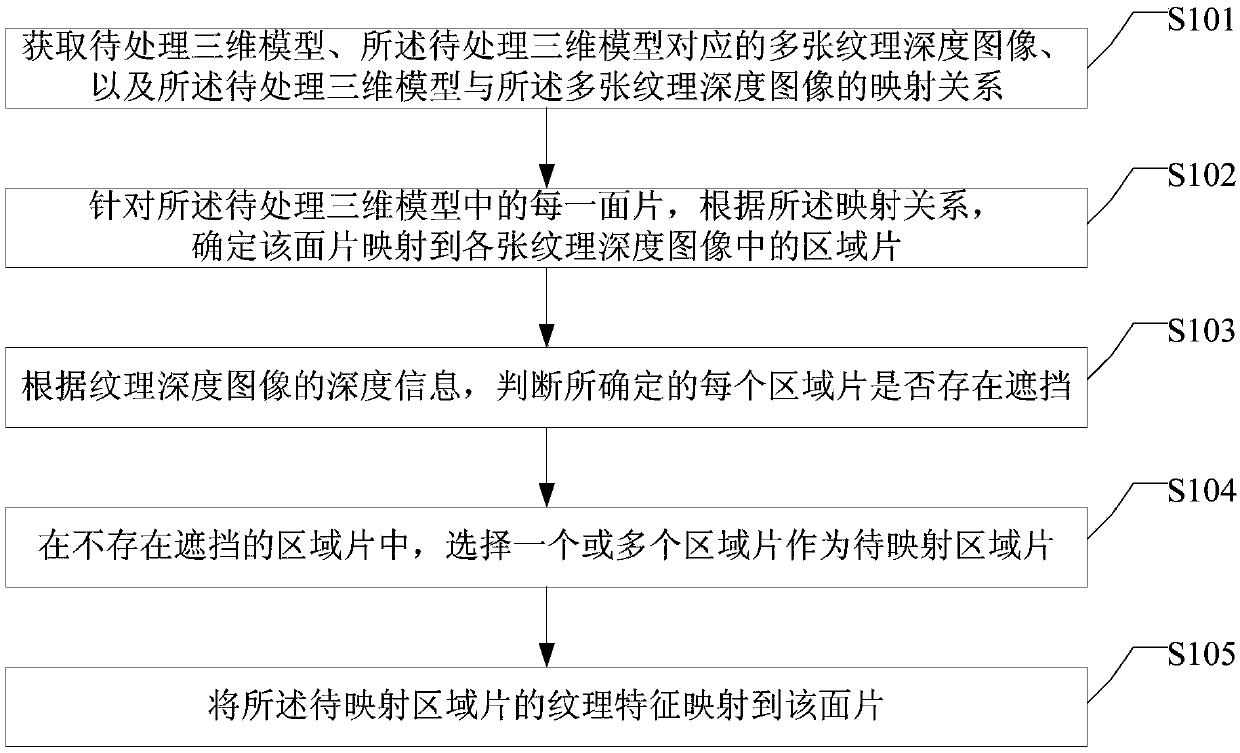
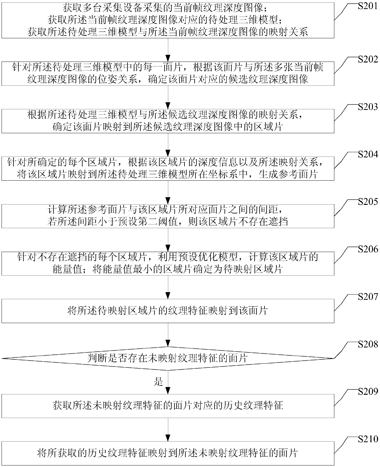
[0138] As an implementation manner, S103 may include:

[0139] For each determined region patch, according to the depth information of the region patch and the mapping relationship, map the region patch into the three-dimensional model to be processed to generate a reference patch; calculate the relationship between the reference patch and the region The distance between the patches corresponding to the patch, the patch corresponding to the region patch is: according to the mapping relationship, the patch mapped to the region patch; if the distance is less than the preset second threshold, the region patch will not There is occlusion.

[0140] Still take the triangular patch F as an example. The patch F contains three vertices A, B, and C. For vertex A, the projection point mapped to the texture depth image I is A'. Suppose A' is in the texture The depth value in the depth image I is d(u A , v A ); then A' is reverse-mapped according to the above mapping relationship, assum...


PUM


Abstract

The embodiment of the invention provides a texture mapping method, device and apparatus based on a three-dimensional model. The method comprises the following steps: for each patch in a three-dimensional model, determining an area patch mapped to a plurality of texture depth images by the patch, selecting the area patch without occlusion as an area patch to be mapped, and mapping texture featuresof the area patch to be mapped to the patch. In the scheme, the facets in the three-dimensional model are mapped by utilizing the texture features of the area patches without shielding in the texturedepth image, and the area patch corresponding to each facet is not shielded, so that the mapping effect is improved.

Description

technical field [0001] The invention relates to the technical field of computer vision, in particular to a texture mapping method, device and equipment based on a three-dimensional model. Background technique [0002] Generally speaking, the 3D model obtained through mesh construction does not have texture features. In order to make the 3D model have a better visual effect, it is usually necessary to perform texture mapping on the 3D model. The existing texture mapping scheme includes: obtaining multiple texture images corresponding to the 3D model, the multiple texture images include targets corresponding to the 3D model, such as vehicle targets, personnel targets, etc.; from the multiple texture images, select a An image with the closest viewpoint, or select the clearest image; according to the mapping relationship between the pixels in the selected texture image and the grid points in the 3D model, map the texture features of the object in the selected texture image to th...

Claims


Application Information

Patent Timeline
IPC IPC(8): G06T19/20
CPCG06T19/20Y02T10/40
Inventor 许娅彤毛慧浦世亮
Owner HANGZHOU HIKVISION DIGITAL TECH
Why Eureka
Eureka Blog
Learn More