Motor end cover and its motor

A technology of motor end cover and end cover, which is applied in the direction of electrical components, electromechanical devices, electric components, etc., can solve the problems of unfavorable operation, low coaxiality, easily damaged bearing internal roller clearance, etc., and achieves convenient installation The effect of disassembly and positioning range change

Active Publication Date: 2020-07-10
山东众泰防爆电机股份有限公司
View PDF9 Cites 0 Cited by
  • Summary
  • Abstract
  • Description
  • Claims
  • Application Information

AI Technical Summary

Problems solved by technology

[0002] When the end cover of the motor is connected with the main body of the motor, the bearing needs to be assembled on the end cover, and the rotor shaft needs to be assembled with the bearing. During the assembly process of the bearing, an interference fit is often used between the end cover and the bearing. Due to the small size of the relative clearance, the interference fit needs to be assembled by extrusion. At this time, it is easy to damage the clearance between the inner rollers of the bearing, which will lead to the situation that the coaxiality is not high, and in the bearing assembly After that, the axial direction of the bearing needs to be positioned with the shaft shoulder of the installation shaft or with a limit sleeve. At this time, it is an assembly department, so the traditional motor end cover is more cumbersome in the process of assembling parts, which is not conducive to to operate

Method used


Image

  • Motor end cover and its motor
  • Motor end cover and its motor
  • Motor end cover and its motor

Examples


Embodiment

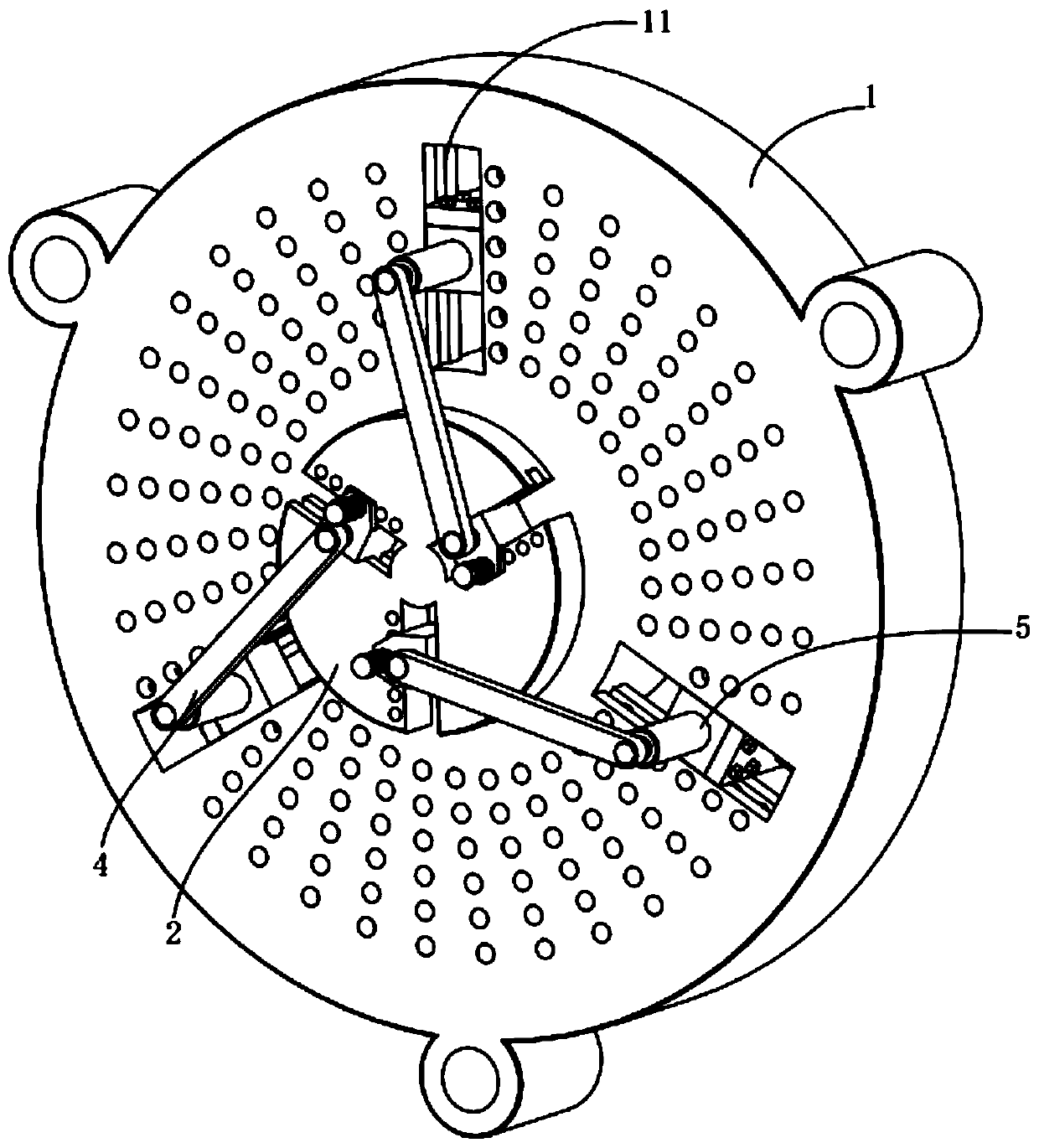
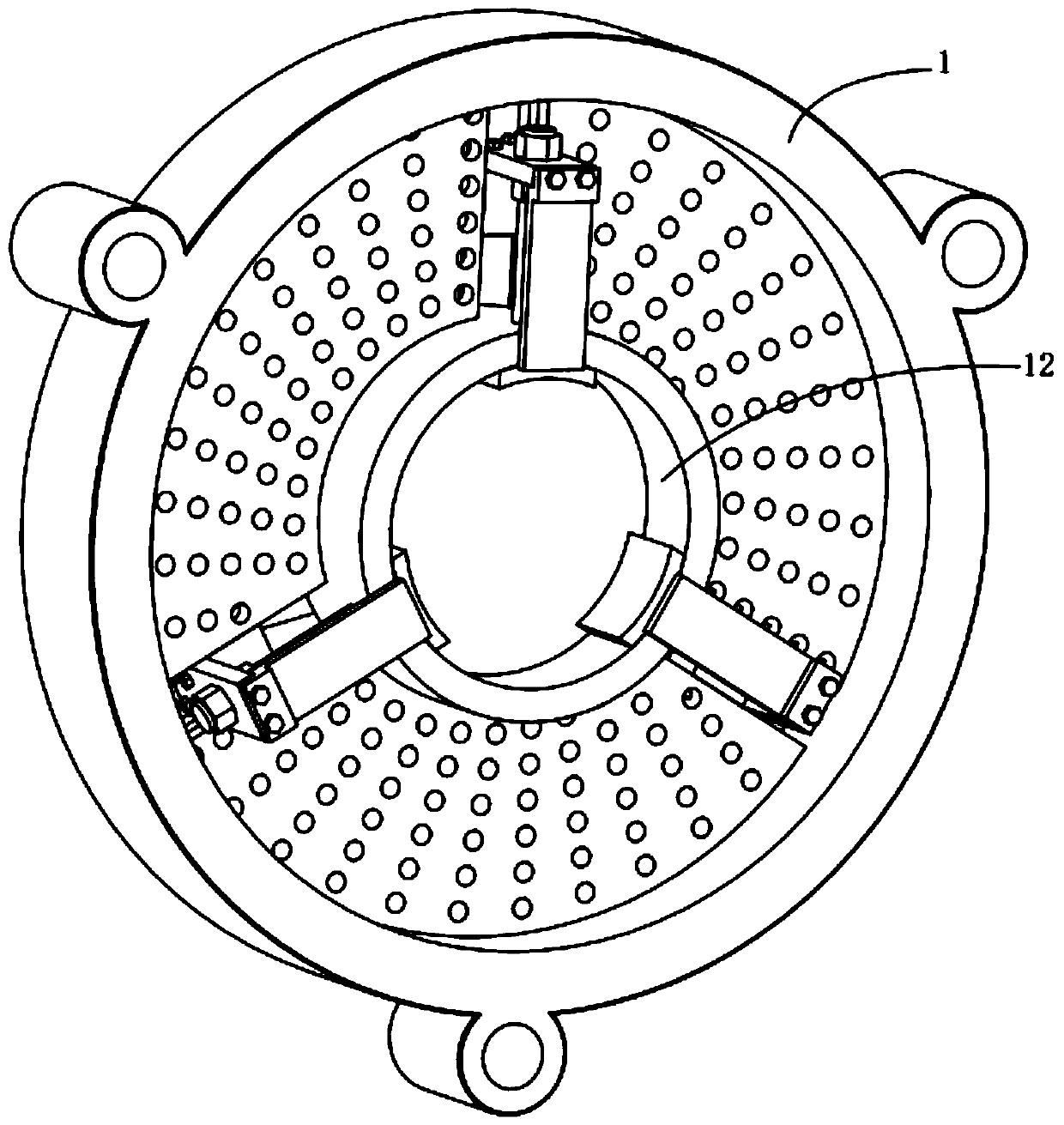
[0021] see Figure 1 to Figure 4 , the present invention provides a technical solution:

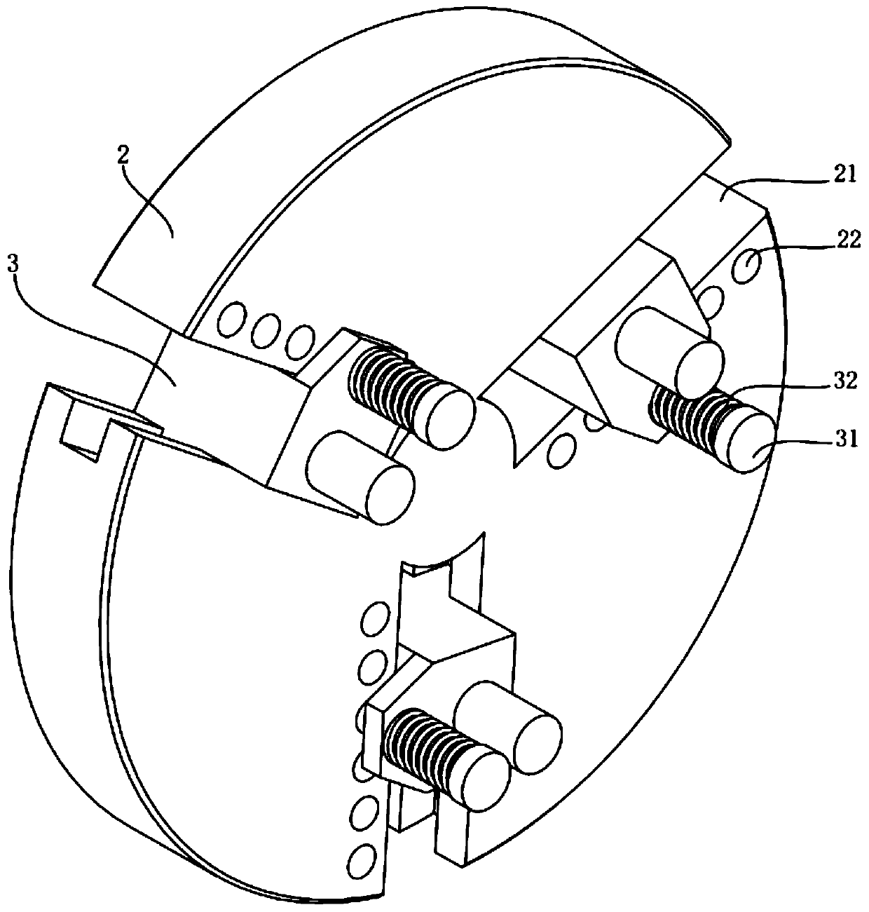
[0022] A motor end cover, including an end cover 1, a turntable 2, a luffing block 3, a connecting rod 4, a slider 5, a transmission plate 6, a radial limit plate 7 and an axial limit plate 8, wherein:

[0023] The end cover 1 is provided with three guide grooves 11 at equal angles and the inside is provided with a bearing installation ring 12, wherein the bearing installation ring 12 is used to install the bearing, and the turntable 2 is installed on the outside of the end cover 1 in rotation. There are three mounting slots 21, and a number of limiting holes 22 are arranged equidistantly beside the mounting slots 21. The three luffing blocks 3 respectively fit in the mounting slots 21 and form a moving pair in the mounting slots 21. The luffing block 3 A limit rod 31 is movable installed, wherein the end of the limit rod 31 extends into the limit hole 22, thereby realizing the limit of ...


PUM


Abstract

The invention provides a motor end cover and a motor thereof. The motor end cover comprises an end cover, a turntable, amplitude variation blocks, a connecting rod, sliders, a transmission plate, a radial limit plate and an axial limit plate. The turntable is rotatably mounted on the outer side of the end cover. Three amplitude variation blocks are mounted on the turntable at an equal angle. Threesliders are mounted on the end cover at an equal angle. The amplitude variation blocks and the sliders are connected through a link. A transmission plate is arranged on the sliders. The radial limitplate and the axial limit plate are arranged on the transmission plate. The radial limit plate is along the inside of a bearing mounting ring. The radial limit plate is flush with the end of the bearing mounting ring. By rotating the turntable and then synchronously driving the sliders to move synchronously, the radial limit plate can achieve radial positioning of a bearing, and the axial limit plate can achieve axial positioning. The assembly process is convenient. The amplitude variation blocks are used to adjust the distance from the center of the turntable to further change the motion range of the sliders, so that the positioning range of the bearing size is changed accordingly.

Description

technical field [0001] The invention relates to the technical field of motor accessories, in particular to a motor end cover and a motor thereof. Background technique [0002] When the end cover of the motor is connected with the main body of the motor, the bearing needs to be assembled on the end cover, and the rotor shaft needs to be assembled with the bearing. During the assembly process of the bearing, an interference fit is often used between the end cover and the bearing. Due to the small size of the relative clearance, the interference fit needs to be assembled by extrusion. At this time, it is easy to damage the clearance between the inner rollers of the bearing, which will lead to the situation that the coaxiality is not high, and in the bearing assembly After that, the axial direction of the bearing needs to be positioned with the shaft shoulder of the installation shaft or with a limit sleeve. At this time, it is an assembly department, so the traditional motor en...

Claims


Application Information

Patent Timeline
Patent Type & Authority Patents(China)
IPC IPC(8): H02K5/15H02K5/16
CPCH02K5/15H02K5/16
Inventor 金怀璧
Owner 山东众泰防爆电机股份有限公司
Why Eureka
Try Eureka