Plastic pipe cold pressing processing device
A processing device and technology for plastic pipes, applied in the field of plastic pipe processing
- Summary
- Abstract
- Description
- Claims
- Application Information
AI Technical Summary
Problems solved by technology
Method used
Image

Examples
specific Embodiment approach 1
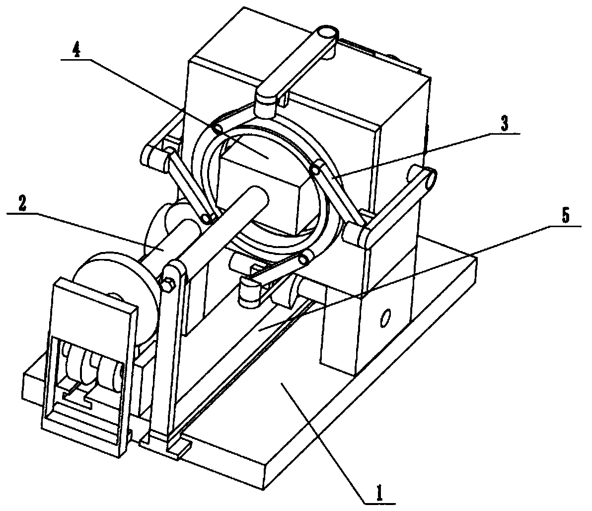
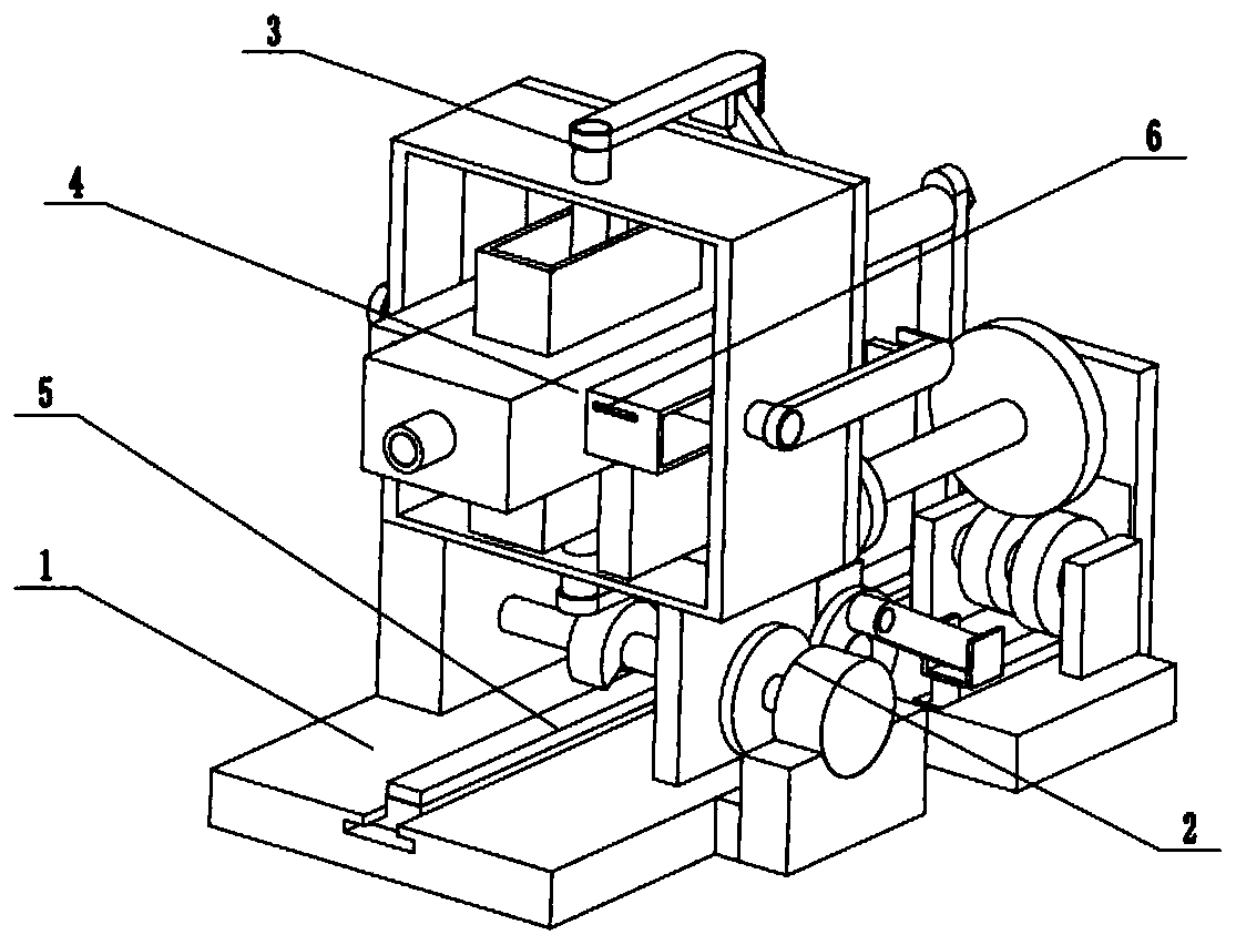
[0033] Such as Figure 1 to Figure 13 As shown, a plastic pipe cold pressing processing device includes a pipe extrusion driving base 1, a joint driver 2, a pipe cold pressing driver 3, a cold pressing center sliding seat 4, an extrusion sliding seat 5 and four plastic pipe condensation extrusion 6, the extrusion sliding seat 5 is slidably connected in the pipe extrusion driving base 1 and the cold pressing center sliding seat 4, the combined driver 2 is fixedly connected to the front end of the pipe extrusion driving base 1, and the combined driver 2 is meshed with the transmission connection The pipe cold pressing driver 3 and the extrusion sliding seat 5, the cold pressing center sliding seat 4 is fixedly connected to the pipe extrusion driving base 1, the pipe cold pressing driver 3 is slidably connected in the cold pressing center sliding seat 4, and the four plastic tubes condense The extruder 6 is uniformly and fixedly connected to the pipe cold pressing driver 3 , and ...
specific Embodiment approach 2
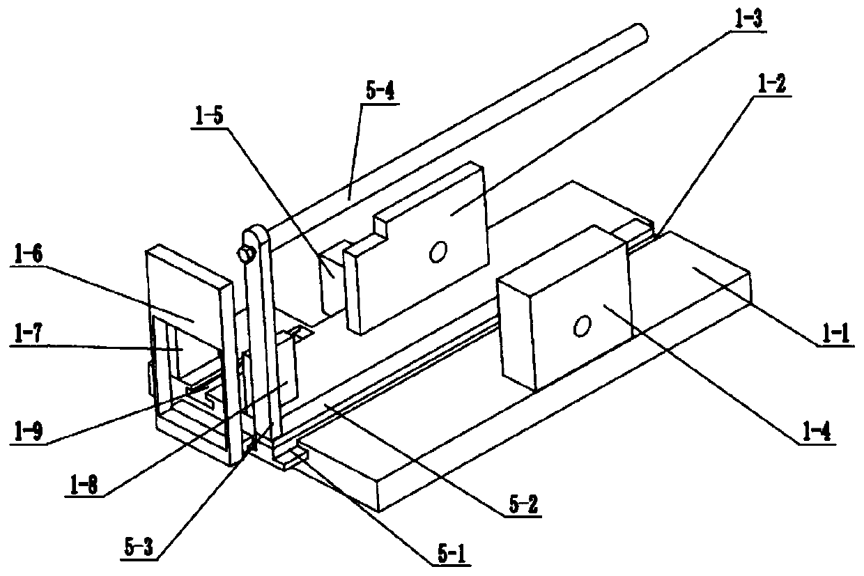
[0035] Such as Figure 1 to Figure 13 As shown, this embodiment will further explain Embodiment 1. The pipe extrusion driving base 1 includes a base 1-1, a central T-shaped chute 1-2, a front fixing seat 1-3, and a rear fixing seat 1-4. , motor fixing seat 1-5, left fixing seat 1-6, connecting front fixing seat 1-7, connecting rear fixing seat 1-8 and front T-shaped chute 1-9, described center T-shaped chute 1- 2 The left and right are set on the middle end of the upper side of the base 1-1, the front fixing base 1-3 and the rear fixing base 1-4 are fixedly connected to the front and rear ends of the upper side of the base 1-1 respectively, and the motor fixing base 1-5 is fixed Connected to the front end of the base 1-1, the left fixed seat 1-6 is fixedly connected to the front side of the left end of the base 1-1, the front fixed seat 1-7 and the rear fixed seat 1-8 are fixedly connected to the base 1-1 The left end of the front T-shaped chute 1-9 is arranged on the left si...
specific Embodiment approach 3
[0037] Such as Figure 1 to Figure 13 As shown, this embodiment will further illustrate the second embodiment. The combined drive 2 includes a drive motor 2-1, a drive rotation shaft 2-2, a main drive gear 2-3, an intermittent 1 / 2 gear 2-4, From drive gear 2-5, from drive hinge shaft 2-6, hinge drive rod 2-7, sliding T-shaped rack 2-8, upper connection gear 2-9, connection shaft 2-10, drive helical gear 2-11 , driven helical gear 2-12, upper rotating shaft 2-13 and extruding reciprocating drive main gear 2-14, described driving motor 2-1 is fixedly connected on the motor holder 1-5, drives rotating shaft 2-2 One end of the drive shaft is connected to the drive shaft of the drive motor 2-1 through a coupling, and the drive shaft 2-2 is connected to the front fixed seat 1-3 and the rear fixed seat 1-4 in rotation, and the main drive gear 2-3 and the intermittent 1 / 2 gears 2-4 are fixedly connected to the drive shaft 2-2, the main drive gear 2-3 is meshed with the slave drive ge...
PUM
 Abstract
Description
Claims
Application Information
 - R&D Engineer
- R&D Manager
- IP Professional
- Industry Leading Data Capabilities
- Powerful AI technology
- Patent DNA Extraction
Browse by: Latest US Patents, China's latest patents, Technical Efficacy Thesaurus, Application Domain, Technology Topic.
© 2024 PatSnap. All rights reserved.Legal|Privacy policy|Modern Slavery Act Transparency Statement|Sitemap