Megasonic cleaning system with buffered cavitation method

Active Publication Date: 2006-09-12
NAURA AKRION INC
View PDF27 Cites 11 Cited by
  • Summary
  • Abstract
  • Description
  • Claims
  • Application Information

AI Technical Summary

Benefits of technology

[0013]The present invention solves these and other problems by providing a system for cleaning wafers, without substantial cavitation damage, through application of an acoustic field to a liquid, where the acoustic field is composed of multiple combined signals, including, for example, a relatively high frequency megasonic signal, a relatively lower frequency signal, and, in one embodiment, a quasi-direct voltage bias signal, such as, for example, a sawtooth waveform of relatively lower frequency compared to the other signals may be added. This results in an unbalanced combined acoustic wave applied to the object to be cleaned, such that the amplitude of the combined positive sound profile effectively

Problems solved by technology

This results in an unbalanced combined acoustic wave applied to the object to be cleaned, such that the amplitude of the combined positive

Method used


Image

  • Megasonic cleaning system with buffered cavitation method
  • Megasonic cleaning system with buffered cavitation method
  • Megasonic cleaning system with buffered cavitation method

Examples


Embodiment Construction

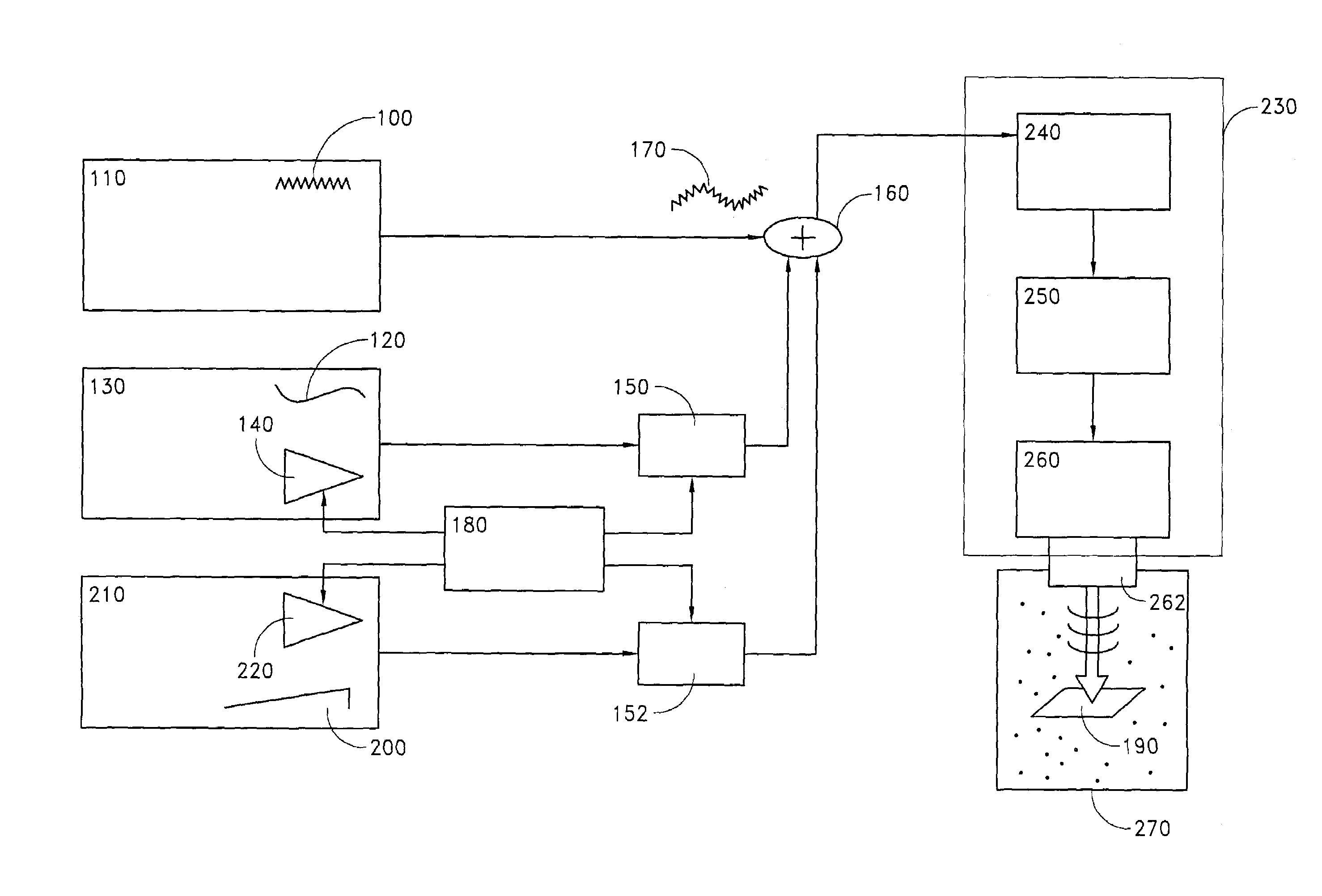
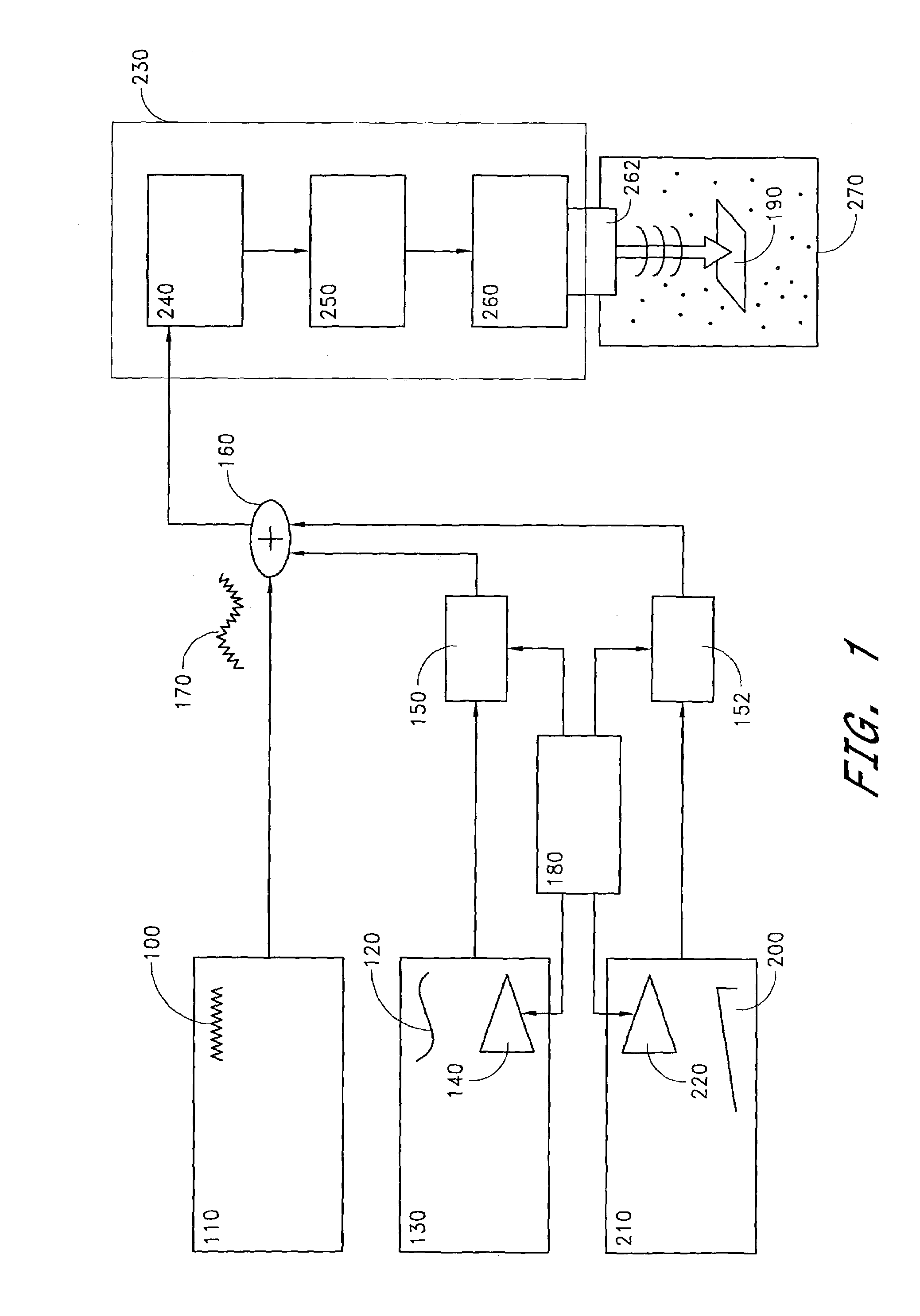
[0026]FIG. 1 is a block diagram showing one embodiment of a biased multiple frequency cleaning system of the present invention. A relatively high frequency signal 100 is generated by a high frequency function generator 110. A relatively low frequency signal 120 is generated by a low frequency function generator 130. Both the high frequency function generator 110 and low frequency function generator 130 advantageously generates electronic wave signals of various profiles, such as, for example, sinusoidal waves, triangular waves, sawtooth waves, step waves, and the like. The acoustic cleaning system can use any two frequency signals where the relatively low frequency signal is of a lower frequency than the relatively high frequency signal. For example, the relatively high frequency signal can be megasonic, above about 800 kHz, and the relatively low frequency signal can be ultrasonic, below about 400 kHz. Advantageously, the system can also, for example, generate two megasonic signals...


PUM

PropertyMeasurementUnit
Poweraaaaaaaaaa
Timeaaaaaaaaaa
Pressureaaaaaaaaaa

Abstract

A wafer cleaning method and system including a combined high frequency signal, a low frequency signal, and in one embodiment a biased voltage signal, allows cleaning particles and impurities off of fine-structured wafers, through application of an acoustic field to the wafer through a cleaning liquid which fosters micro-bubble formation for effective cleaning while buffering micro-bubble growth which would otherwise damage the wafer.

Description

BACKGROUND OF THE INVENTION[0001]1. Field of the Invention[0002]This invention relates to methods and systems for cleansing semiconductor wafers and other items requiring extremely high levels of cleanliness, while minimizing damage to the wafer or object being cleaned.[0003]2. Description of the Related Art[0004]Systems employing megasonic or ultrasonic cleaning processes have been widely used to remove particles and defects from objects such as silicon wafers used in the semiconductor industry. The wafers are sometimes cleaned, for example, in a liquid or fluid into which megasonic energy is propagated. These megasonic cleaning systems safely and effectively remove particles from objects, where a system typically includes a signal generator, a piezoelectric transducer, and a transmitter, among other components. The transducer is electrically excited by a signal that causes it to vibrate, and the transmitter transmits the resulting vibration into the cleaning liquid in a processing...

Claims


Application Information

Patent Timeline
IPC IPC(8): B08B6/00B08B3/12
CPCB08B3/12Y10S438/906
Inventor WU, YIFRANKLIN, COLE S.FRASER, BRIANNICOLOSI, THOMAS
Owner NAURA AKRION INC
Why Eureka
Try Eureka