Reaming tool and process for its production

a technology of reaming tools and cutting materials, which is applied in the direction of reaming tools, boring/drilling equipment, turning apparatuses, etc., can solve the problems of inability to meet the requirements of the envelope surface, and inability to run around the envelope surface at firs

Inactive Publication Date: 2001-09-27
BECK GMBH & CO AUGUST
View PDF0 Cites 12 Cited by
  • Summary
  • Abstract
  • Description
  • Claims
  • Application Information

AI Technical Summary

Benefits of technology

[0013] By the use of a blank which has on its envelope surface substantially rectilinear or helical groove-shaped recesses, into which high hardness cutting materials are sintered, a cost-favorable production and manufacture of a reaming tool can be provided. An expensive preparation for the introduction of seatings for chip removal elements and / or guide elements is dispensed with by the hard cutting material already present in the blank, since the sintered-in hard material layers can be used as chip removal strips and / or guide strips specifically according to the application, and can be machined to dimension. Furthermore, this advantageous embodiment makes it possible for the shaft of the reaming tool to be made of a cost-favorable material which can be positively connected, but however preferably non-positively connected, to the shaped head.
[0016] However, by the constitution of a reaming tool according to the invention, the constitution of a reaming tool with twisted chip formation elements and / or guide elements is attained, which heretofore has not been possible. This can be made possible, for example, for a multi-cutter reamer which has cutters of high hardness cutting materials. A single cutter reaming tool with guide strips can likewise be provided, in which both the chip removal element and also the guide elements, or one of the two, is twisted. A considerable improvement can thereby be attained as regards the processing quality, the speed, and also the life of the tool. This is based on the fact that the chip removal elements and guide elements are sintered into the base body of the shaped head, so that a material joint of higher quality than the usual brazed joint can thereby result. Furthermore, the labor-consuming brazed joints and the production of seatings for plates or guide strips are dispensed with, together with the associated risks of defective brazed places which can arise because of negligent cleaning of the contact surfaces.
[0025] A reaming tool can be constituted according to the invention, which is substantially determined by the reduction of the individual working steps. By the employment of a blank with high hardness cutting materials provided in groove-shaped recesses on a shaft, the costly preparation of a base body in order to seat chip removal elements and guide elements, and the subsequent brazing of these, can be dispensed with. By the grinding of the blank to dimension, a rapid shaping of a reaming tool can be given by means of a single clamping. At the same time, a high constancy of dimensions can be given, since repeated resetting of the workpiece is not required. A reaming tool can thus be produced by the process according to the invention, in which both the at least one chip removal element and also the at least one guide element are constituted by the high hardness cutting material arranged on the blank.

Problems solved by technology

An expensive preparation for the introduction of seatings for chip removal elements and / or guide elements is dispensed with by the hard cutting material already present in the blank, since the sintered-in hard material layers can be used as chip removal strips and / or guide strips specifically according to the application, and can be machined to dimension.
The use of blanks with high hardness cutting materials provided in groove-shaped recesses and running around the envelope surface at first appears to be erroneous.
Furthermore, end millers operate at relatively high cutting speeds and depths of cut, so that quite other forces act on a head of an end miller.
The use of such blanks with high hardness cutting materials arranged in grooves and extending substantially coaxial to the rotation axis therefore would appear to be unsuitable, particularly when costs are taken into account.
The same holds for the use of reaming tools because of the forces, parameters and requirements which deviate from milling technology, and which at first sight make the use appear to be erroneous to form the reaming tool by means of a blank which has on its envelope surface substantially rectilinear or helical groove-shaped recesses, into which high hardness cutting material is sintered.
However, by the constitution of a reaming tool according to the invention, the constitution of a reaming tool with twisted chip formation elements and / or guide elements is attained, which heretofore has not been possible.
Furthermore, the labor-consuming brazed joints and the production of seatings for plates or guide strips are dispensed with, together with the associated risks of defective brazed places which can arise because of negligent cleaning of the contact surfaces.

Method used


Image

  • Reaming tool and process for its production
  • Reaming tool and process for its production
  • Reaming tool and process for its production

Examples


Embodiment Construction

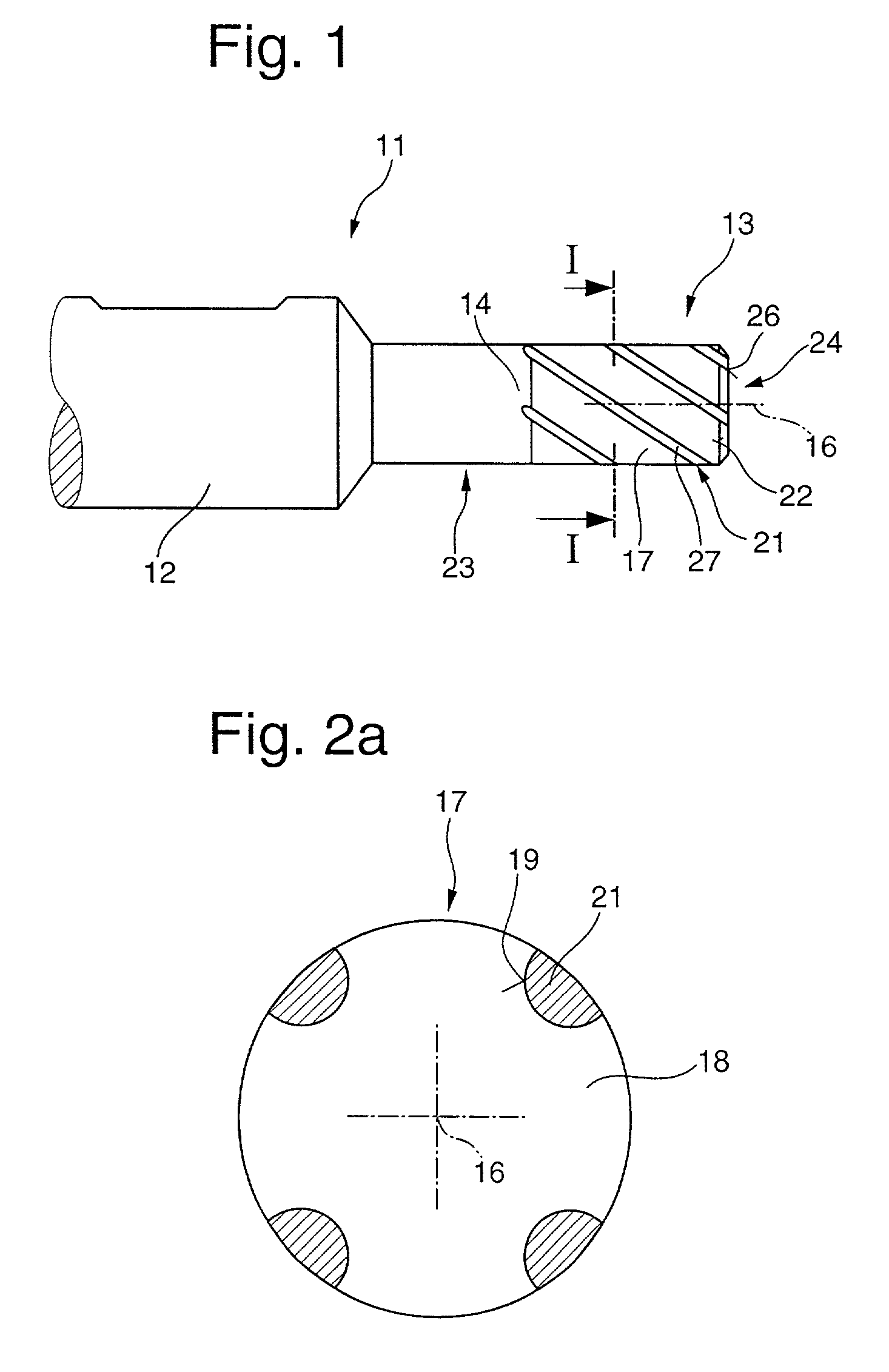
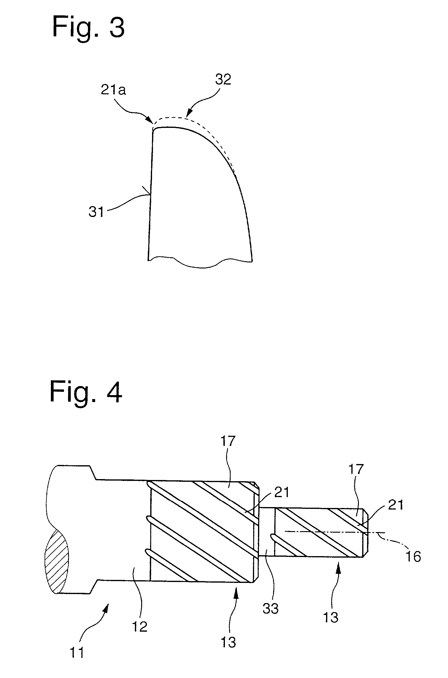
[0033] A reaming tool is shown in FIG. 1, which is used for the fine machining of boreholes. The reaming tool 11 has a shaft 12, which serves for clamping on a machine tool. A shaped head 13 for shaping is arranged on the shaft 12, preferably by means of a material joint to the shaft 12. Alternatively, a positive and / or non-positive joint can be provided. The shaped shaping head 13 advantageously has a centering nose 14 by means of which the shaped head 13 can be positioned rotationally symmetrically to the shaft 12. Further geometrical centering means can be provided so that the shaped head 13 and the shaft 12 have a common axis of rotation 16.

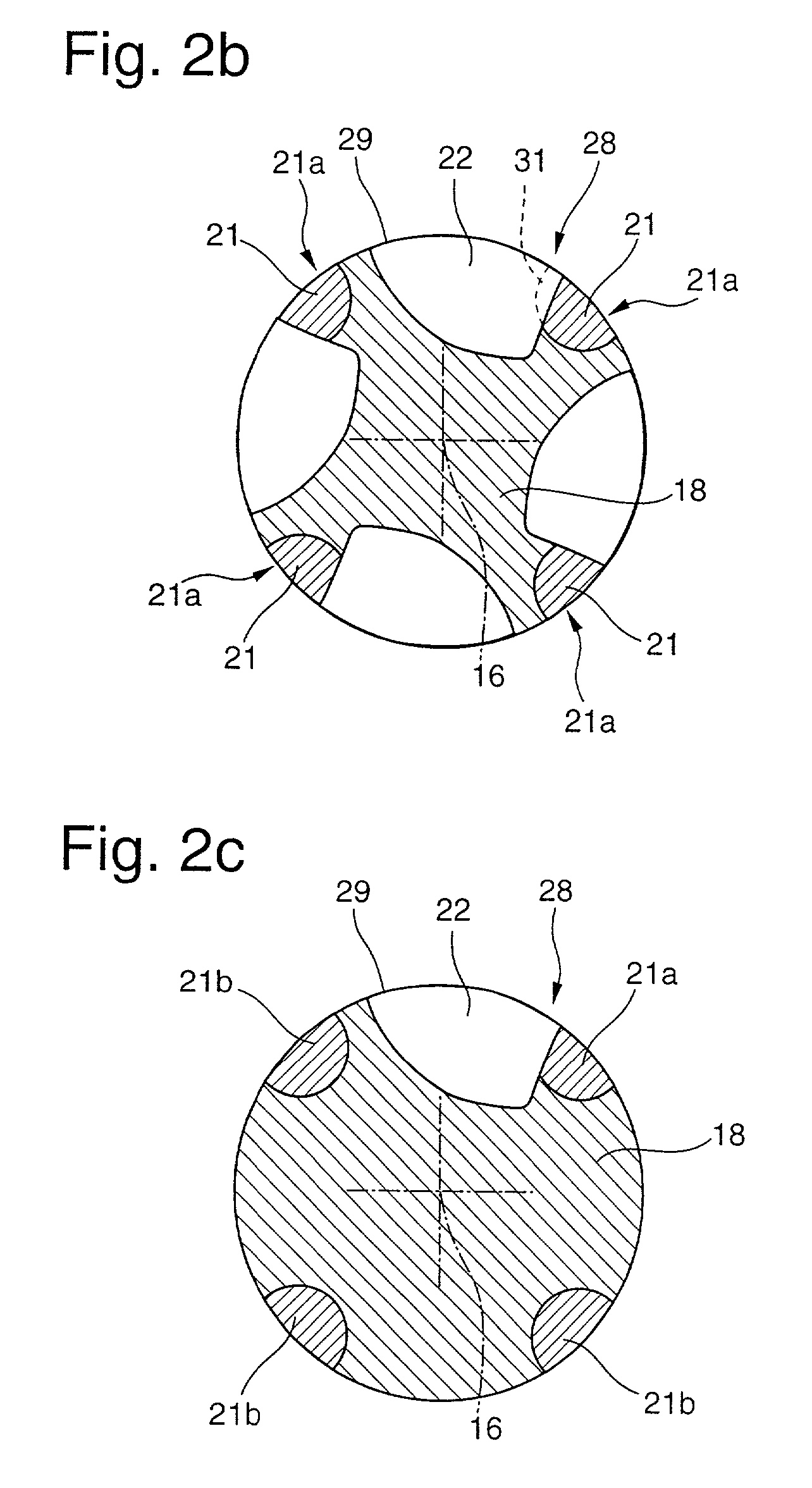
[0034] The shaped head 13 for shaping is machined from a blank 17. The blank 17 has a cross section as shown in FIG. 2a. Groove-shaped recesses 19 are provided in a base body 18 of the blank 17, and high hardness cutting materials 21 are sintered into them. In the embodiment according to FIG. 2a, the groove-shaped recess 19 is of a semicircul...


PUM

PropertyMeasurementUnit
chip angleaaaaaaaaaa
hardnessaaaaaaaaaa
diametersaaaaaaaaaa

Abstract

A multi or single cutter reaming tool has a shaft and a shaped head with at least one cutter. The shaped head is produced from a blank having a base body of a base material on its envelope surface with at least one rectilinear or helical groove-shaped recess running around it, into which high hardness cutting material is sintered. The high hardness cutting material includes at least one cutter having cutting surfaces formed by the introduction of a chip groove by a grinding wheel into the base body and movement of the grinding wheel toward the high hardness cutting material.

Description

CROSS-REFERENCES TO RELATED APPLICATIONS[0001] Not applicable.[0002] Not applicable.[0003] 1. Technical Field[0004] This is a Divisional of U S. patent application Ser. 09 / 253,308 filed Feb. 19, 1999 of the same inventor.[0005] The invention relates to a reaming tool and a process for its production.[0006] Reaming tools are used for the fine machining of boreholes and therefore require a precise arrangement and design of chip removal elements and guide elements. In particular, a high degree of dimensional accuracy is desired.[0007] 2. Background Art[0008] Reaming tools have already been known in which the chip removal elements or guide elements are set into a base body, for example by brazing or by adhesion. It has become known from German Patent DE 196 21 813 A1 to form a corresponding seating for the positioning of guide strips in order to make the seating of the inset chip removal elements and guide elements precise, so that these can be exactly positioned with respect to the bas...

Claims


Application Information

Patent Timeline
Patent Type & Authority Applications(United States)
IPC IPC(8): B23D77/02B23P15/46
CPCB23D77/02B23D2277/82B23P15/46Y10T408/5586Y10T408/81Y10T408/906Y10T408/905Y10T407/26Y10T407/1966
Inventor PAPAJEWSKI, JORG
Owner BECK GMBH & CO AUGUST
Why Eureka
Try Eureka