A method for drawing edge contour lines of laser spot size

A technology of laser spot and edge profile, applied in the direction of using optical devices, instruments, measuring devices, etc.

Active Publication Date: 2021-04-06
CHANGCHUN UNIV OF SCI & TECH
View PDF8 Cites 0 Cited by
  • Summary
  • Abstract
  • Description
  • Claims
  • Application Information

AI Technical Summary

Problems solved by technology

[0003] Aiming at the deficiencies of the existing method for drawing the edge contour of the spot size, the purpose of the present invention is to propose a method for drawing the edge contour of the laser spot size, which solves the point of the edge contour of the spot size in any angle direction of the laser spot image by using the light intensity second moment method position, connect the edge contour points to obtain the edge contour of the spot size, scientifically and comprehensively reflect the spatial characteristics of the laser spot

Method used


Image

  • A method for drawing edge contour lines of laser spot size
  • A method for drawing edge contour lines of laser spot size
  • A method for drawing edge contour lines of laser spot size

Examples


Embodiment 1

[0030] Embodiment 1 A laser spot size edge contour drawing method.

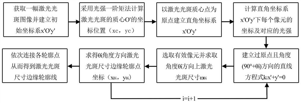
[0031] as attached figure 1 As shown, a kind of laser spot size edge outline drawing method provided by the present invention comprises the following steps:

[0032] Step 1. Obtain a laser spot image with a pixel number width W and a pixel number length H; the image has no background noise, and there is no saturated pixel in the image; taking the upper left corner of the image as the origin O, The horizontal direction to the right is the positive direction of the x-axis, and the vertical downward direction is the positive direction of the y-axis to establish a rectangular coordinate system x0y; extract the coordinate value (x) of each pixel in the image a ,y b ) and the corresponding light intensity value I(x a ,y b );

[0033] Step 2. Use formula (1) and formula (2) to calculate the coordinate position (x c ,y c );

[0034]

[0035]

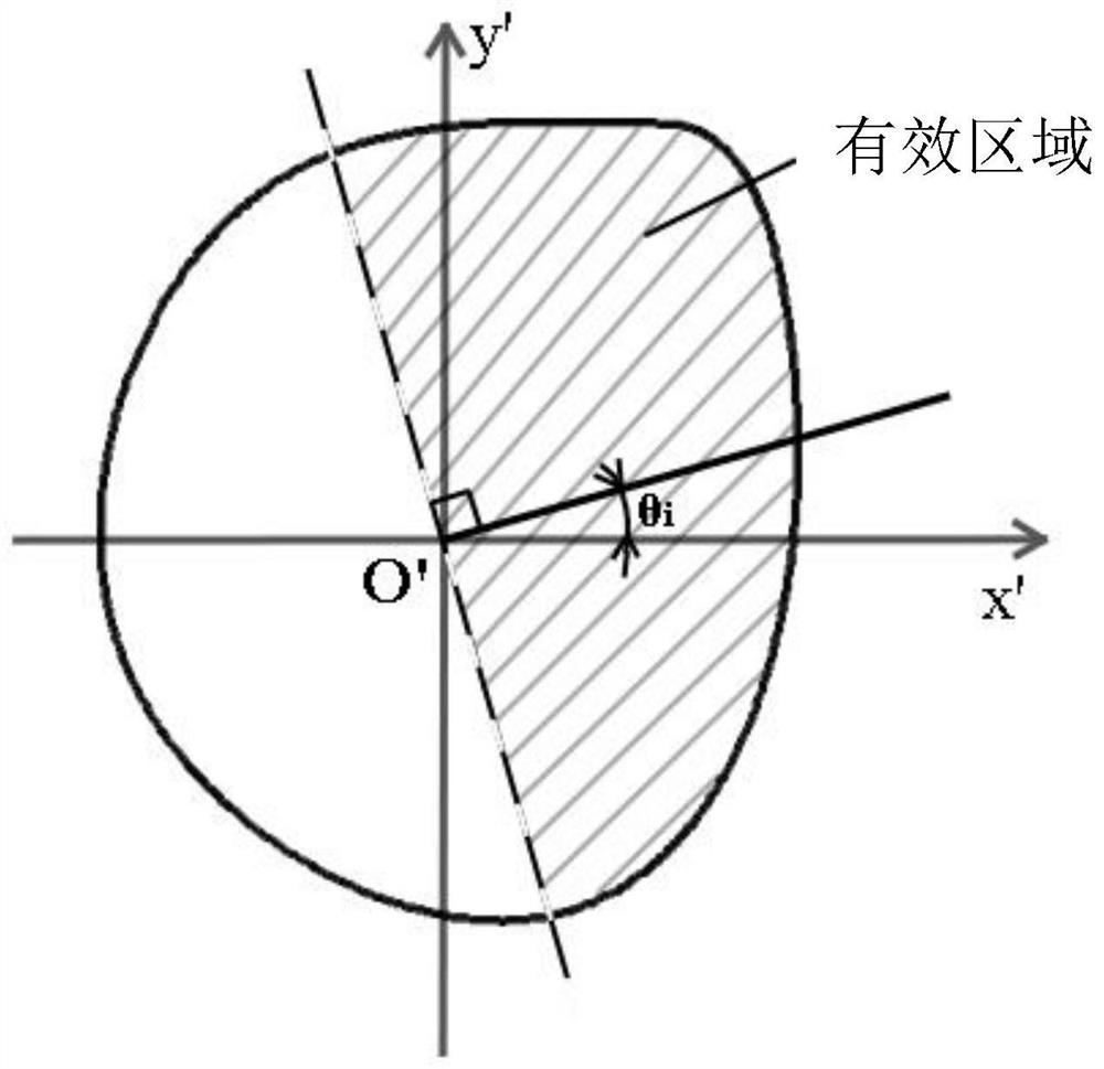
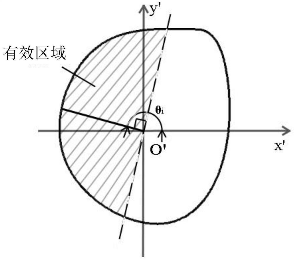
[0036] Step 3. Taking the center of mass O' as the coordinat...


PUM


Abstract

The invention discloses a method for drawing the edge contour line of the laser spot size. First, the position of the centroid of the laser spot is obtained, and a rectangular coordinate system is established with the centroid as the coordinate origin O'. By solving θ i The angle corresponds to each effective pixel (x' a ,y' b ) to the coordinate origin O' and the angle is 90°+θ i Straight line displacement d iab and laser spot size ω θi , so that θ i The coordinates of the edge contour points of the laser spot size corresponding to the angular direction (x θi ,y θi ), by connecting different θ i The edge contour points of the laser spot size in the angular direction, so as to draw a laser spot size edge contour line. The present invention draws the edge contour curve of the spot size by connecting each edge contour point, which intuitively reflects the geometric shape of the laser spot size.

Description

technical field [0001] The invention relates to a laser spot size edge contour drawing method, belonging to the technical field of lasers. Background technique [0002] In the design, manufacture and application of lasers, the laser spot parameters in the vertical axis section are an important index to evaluate the quality of the laser spot, and the edge contour of the laser spot size can intuitively reflect the geometry of the laser spot. At present, there are mainly two methods for drawing the edge contour of the laser spot size: one is to extract 1 / e2 of the maximum light intensity of the spot as the threshold, and the edge line of the spot size greater than this threshold is used as the edge contour of the spot size; the other One is to use the light intensity second-order moment method to obtain the spot size in the X direction or at the same time in the X direction and Y direction, and then perform circle fitting or ellipse fitting of the edge profile of the spot size....

Claims


Application Information

Patent Timeline
Patent Type & Authority Patents(China)
IPC IPC(8): G01B11/24
CPCG01B11/24
Inventor 张思博车英王菲刘长青李玉瑶黄一芮赵亚超陈燨底才翔田明
Owner CHANGCHUN UNIV OF SCI & TECH
Why Eureka
Try Eureka