Video camera position adjustment device

An adjustment device and camera technology, applied in the field of photography, can solve problems such as limiting the quality of photography, limiting the scope of application of photography, and the inability to lift the camera, etc., to achieve high efficiency, good quality, and improved shooting effects

Pending Publication Date: 2019-12-24
GUIZHOU MINZU UNIV
View PDF0 Cites 4 Cited by
  • Summary
  • Abstract
  • Description
  • Claims
  • Application Information

AI Technical Summary

Problems solved by technology

[0005] 1. The existing camera position adjustment device only adjusts the camera position, but cannot adjust the angle of the camera, thus greatly limiting the quality of photography
[0006] 2. Most of the existing camera position adjustment devices are fixed in one position a

Method used


Image

  • Video camera position adjustment device
  • Video camera position adjustment device
  • Video camera position adjustment device

Examples


Embodiment

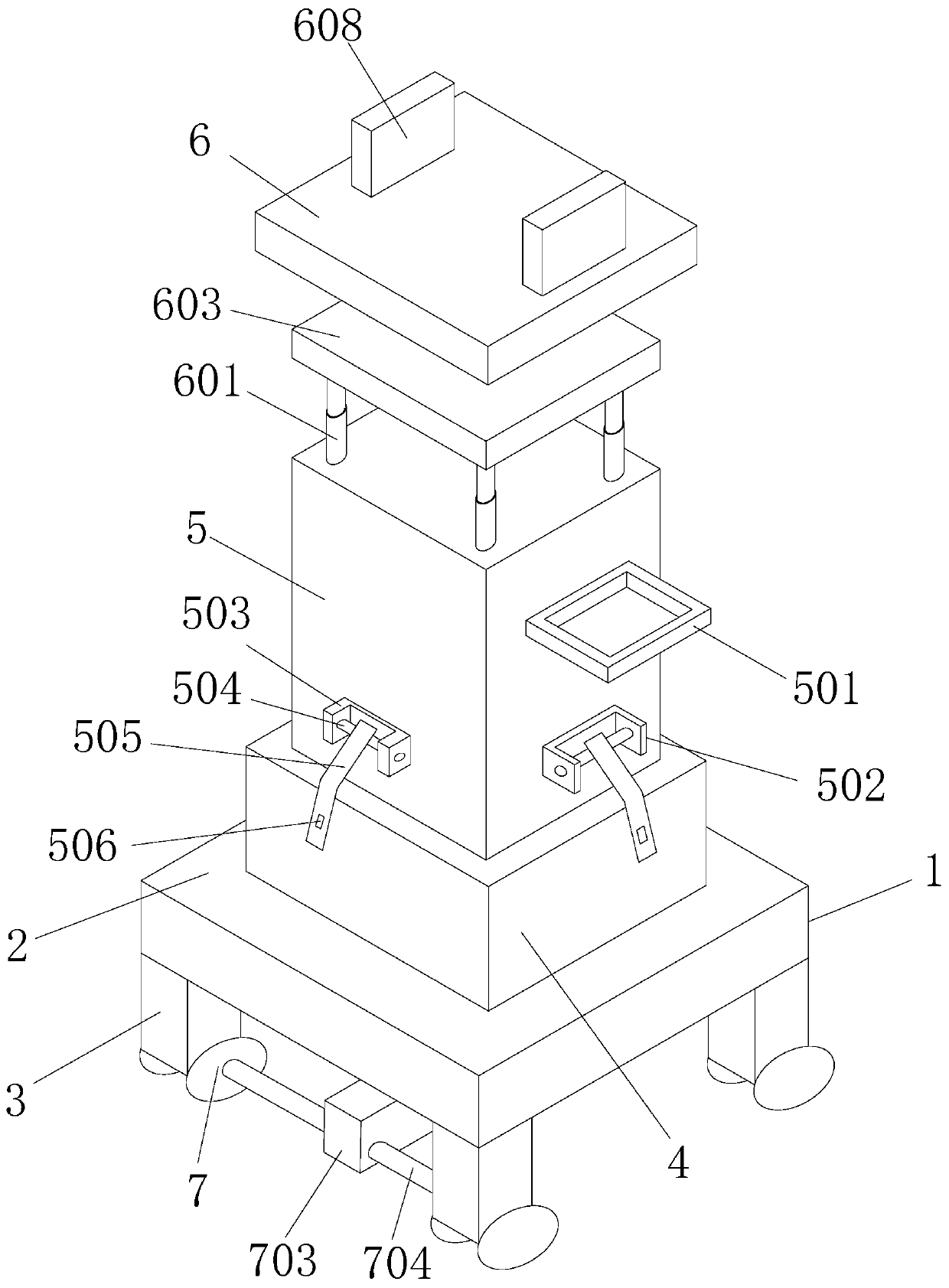
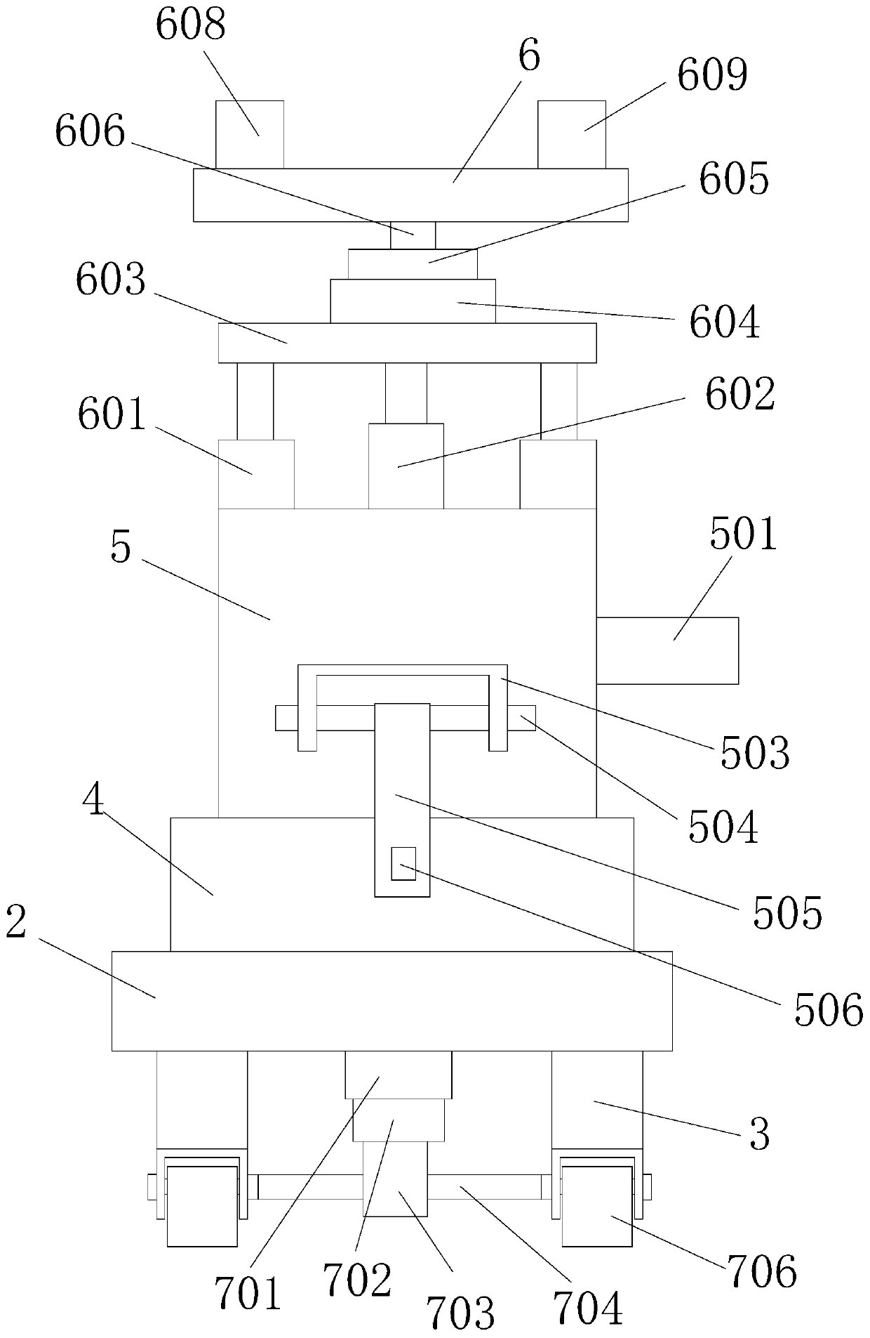
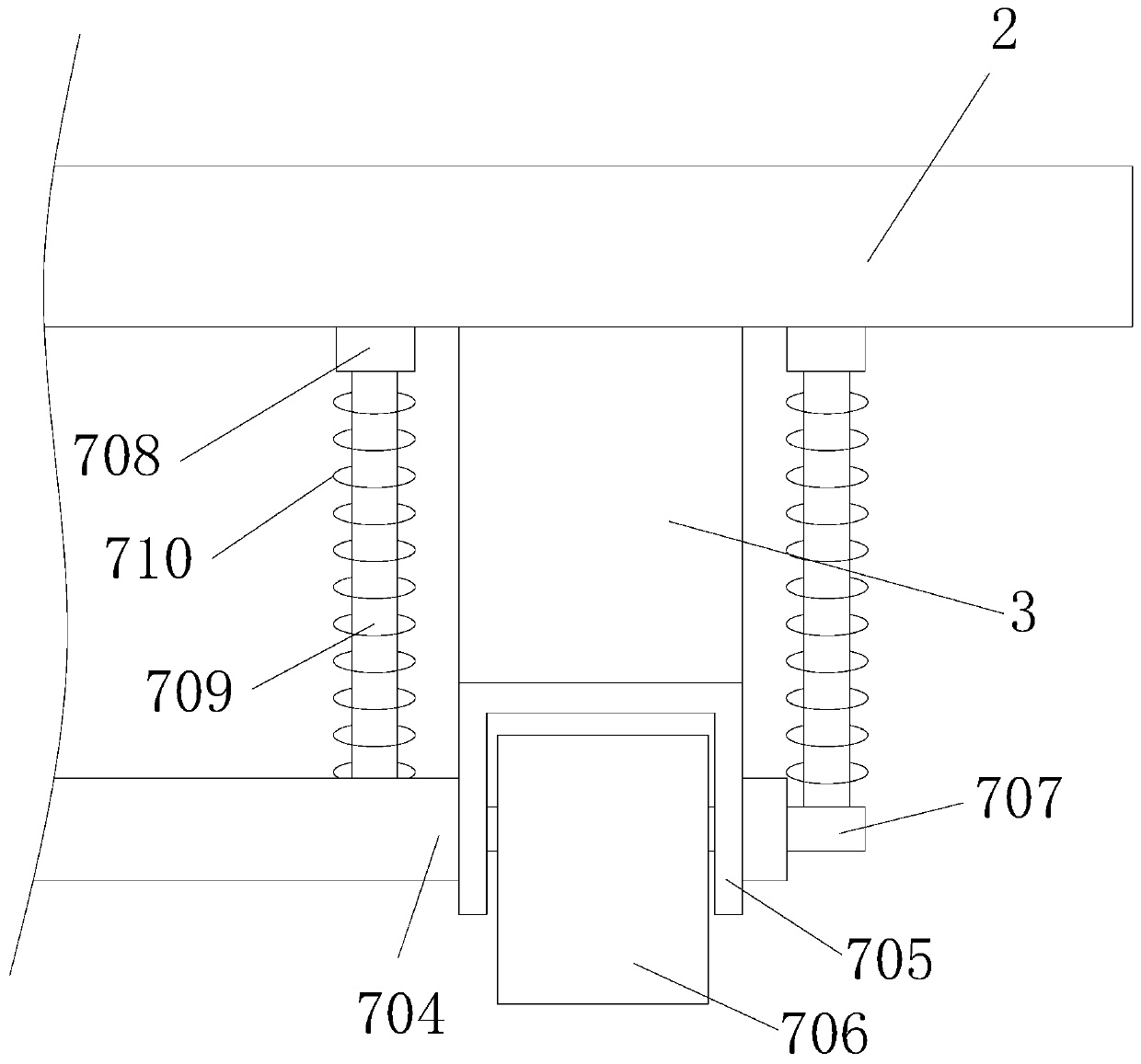
[0038] Such as Figure 1-Figure 3 As shown, this embodiment provides a camera position adjustment device, including: a base 1 , a positioning platform 4 , a column 5 , a lifting and rotating platform 6 and a running part 7 .

[0039]The positioning platform 4 is fixedly connected to the top of the base 1, wherein the positioning platform 4 is a cube, and the top of the positioning platform 4 is provided with a placement groove. The upright column 5 is a cuboid, and the bottom end of the upright column 5 is fitted and connected in the placement groove. The elevating turntable 6 is arranged on the top of the column 5, and an elevating rotating part is arranged between the elevating rotating table 6 and the upright column 5, and the elevating rotating table 6 lifts or rotates relative to the upright column 5 through the elevating rotating part. Wherein the lifting rotary table 6 is used to place the camera, and the camera moves up and down and rotates following the lifting rotar...


PUM


Abstract

The invention relates to a video camera position adjustment device, and belongs to the camera shooting technology field. The video camera position adjustment device comprises a bottom seat, a positioning table, a stand column, a lifting rotation table and a walking component, wherein the positioning table is fixedly connected with the top end of the bottom seat, a placing groove is formed in the top end of the positioning table, the bottom end of the stand column is connected in the placing groove in an embedded mode, the lifting rotation table is arranged above the stand column, a lifting rotation component is arranged between the lifting rotation table and the stand column, the lifting rotation table moves up and down and/or rotates relatively to the stand column through the lifting rotation component, the walking component is arranged at the bottom end of the bottom seat, and the bottom seat is driven to move through the walking component. The video camera position adjustment devicecan conveniently adjust shooting angles of a video camera, and meanwhile can perform moving shoot, achieves high shoot quality, and cannot cause an obvious shaking phenomenon.

Description

technical field [0001] The invention belongs to the technical field of photography, and in particular relates to a camera position adjustment device. Background technique [0002] When shooting a shot in a news interview, the camera needs to move continuously, that is, to shoot by moving the camera position, or changing the optical axis of the lens, or changing the focal length of the lens in a shot. The pictures captured by this shooting method are called moving pictures. Such as: push lens, pull lens, pan lens, shift lens, follow lens, lift lens and comprehensive motion lens formed by push, pull, shake, move, follow, lift camera and comprehensive motion camera. [0003] Among them, there are mainly two shooting methods for mobile photography, one is that the camera is placed on various moving objects; the other is that the cameraman carries the camera on his shoulder and shoots through the movement of the human body. Both of these shooting forms should strive for a stabl...

Claims


Application Information

Patent Timeline
IPC IPC(8): F16M11/04F16M11/08F16M11/18F16M11/32F16F15/04G03B17/56
CPCF16M11/04F16M11/08F16M11/18F16M11/32F16F15/046G03B17/561
Inventor 董琪李静宇
Owner GUIZHOU MINZU UNIV
Why Eureka
Try Eureka