Clamping mechanism and electroplating device

A clamping mechanism and clamping frame technology, applied in the electrolysis process, electrolysis components, etc., can solve problems such as difficulty in meeting, and achieve the effect of ensuring accuracy and facilitating processing and preparation.

Pending Publication Date: 2019-12-31
KUNSHAN DONGWEI MACHINERY CO LTD
View PDF0 Cites 0 Cited by
  • Summary
  • Abstract
  • Description
  • Claims
  • Application Information

AI Technical Summary

Problems solved by technology

[0005] Therefore, the technical problem to be solved by the present invention is that when the existing clamping mechanism clamps the plate, it is difficult to meet the defect of preventing the plate from falling without damaging the plate.

Method used


Image

  • Clamping mechanism and electroplating device
  • Clamping mechanism and electroplating device
  • Clamping mechanism and electroplating device

Examples


Embodiment 1

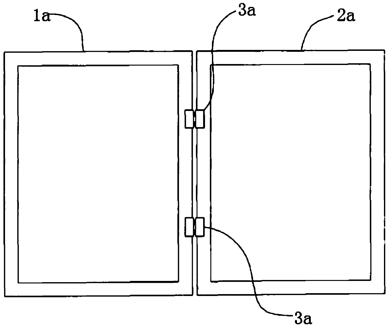
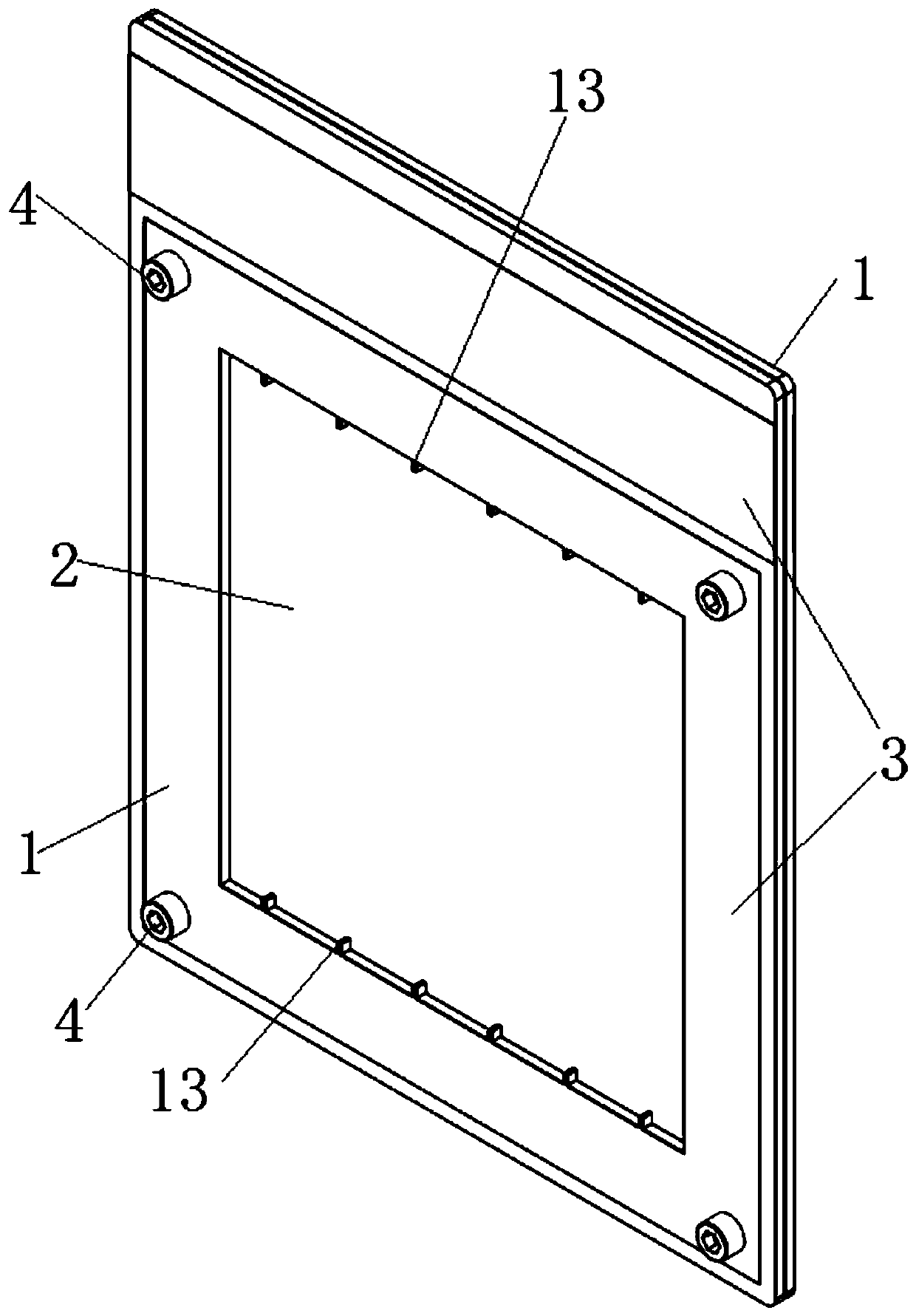
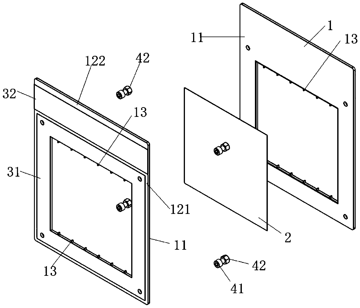
[0057] This embodiment provides a clamping mechanism, such as Figure 2 to Figure 6 As shown, two clip frames 1 that are relatively movable and detachably fixed are included. For the convenience of expression, the two clip frames 1 are respectively expressed as the first clip frame (such as figure 2 The left clip frame in ) and the second clip frame (such as figure 2 in the right clip box).

[0058] The two clip frames 1 can be switched between the limit state and the open state, wherein, in the limit state, the first clip frame and the second clip frame are stacked and fixedly connected, and the hollow inner cavity of the two clip frames 1 overlap; as Figure 4 , Figure 5 and Figure 6 As shown, the first clamping frame and the second clamping frame are adjacent to the inner wall of the inner cavity of the hollow cavity to form a notch at the abutting position to communicate with the limiting groove 14 of the hollow inner cavity, and the limiting groove 14 is suitable...

Embodiment 2

[0091] This embodiment provides an electroplating device, including any one of the clamping mechanisms provided in Embodiment 1, a plurality of electroplating tanks, and a plurality of electroplating fixtures. Wherein, a plurality of electroplating tanks are arranged in sequence, and the tank walls of two adjacent electroplating tanks are connected, and the electroplating tanks are used to place electroplating chemicals.

[0092] A plurality of electroplating fixtures are fixed on the delivery mechanism, and a plurality of electroplating fixtures will be clamped on one end of the clamping mechanism provided in Embodiment 1 (such as, preferably, clamped on the second conductive part of clamp frame 1 in Embodiment 1). area 122), so that the clamping mechanism extends vertically in the air; the peripheral edges of the plate 2 are embedded in the limiting groove 14 of the clamping mechanism, and the rest of the plate 2 is exposed in the hollow cavity of the clamping frame 1. At th...


PUM


Abstract

The invention discloses a clamping mechanism and an electroplating device. The clamping mechanism comprises two clamping frames which are movably and detachably fixed. The electroplating device comprises the clamping mechanism. The two clamping frames can be switched between the limiting state and the opened state. In the limiting state, the circumferential inner side walls, adjacent to hollow inner cavities, of the two clamping frames form groove openings in an enclosing manner in the abutting positions, and the groove openings are communicated with limiting grooves of the hollow inner cavities. The limiting grooves are used for allowing the peripheral edge of a plate to be embedded thosein. The limiting groove bottoms are used for limiting the length direction and the width direction ofthe plate. The plate cannot be separated from the limiting grooves, and the phenomenon of falling of the plate is avoided. Meanwhile, the distance L1 between the two groove walls of the limiting grooves is larger than the thickness L0 of the plate so as to form a movable gap L2 allowing the plate to move between the two groove walls, and the plate is not subjected to clamping force of the two groove walls of the limiting grooves in the thickness direction of the plate, so that the phenomenon that the surface of the plate is damaged due to too large clamping force is avoided.

Description

technical field [0001] The invention relates to the technical field of clamps, in particular to a clamping mechanism and an electroplating device. Background technique [0002] In the electroplating industry, it is necessary to electroplate a metal layer with a required thickness on the plate. The plate needs to be clamped by a clamping mechanism, and the plate is suspended in the corresponding electroplating tank so that the metal ions in the solution in the electroplating tank are electroplated. on the surface of the plate. For example, electroplating metal copper on a silicon wafer with a conductive layer on the surface, or electroplating copper on the surface of a circuit board. [0003] Most of the existing clamping mechanisms such as figure 1 The shown structure comprises a first clamping frame 1a and a second clamping frame 2a, one end of the first clamping frame and the second clamping frame is hingedly connected by a hinge 3a, and the first clamping frame and the ...

Claims


Application Information

Patent Timeline
Patent Type & Authority Applications(China)
IPC IPC(8): C25D17/06
CPCC25D17/06
Inventor 韩友生李阳照方荣平
Owner KUNSHAN DONGWEI MACHINERY CO LTD
Why Eureka
Try Eureka