Multi-station induction heating circuit and heating and control method thereof

An induction heating, multi-station technology, applied in induction heating control, induction heating and other directions, can solve the problem that the control circuit cannot accurately capture and determine the heating situation of the heating coil, the workpiece cannot obtain the ideal heating effect, and the magnetic field signal is disordered. Good heating effect, high reliability of the circuit as a whole, and the effect of reducing processing costs

Pending Publication Date: 2020-01-07
深圳市双平电源技术有限公司
View PDF1 Cites 1 Cited by
  • Summary
  • Abstract
  • Description
  • Claims
  • Application Information

AI Technical Summary

Problems solved by technology

[0009] For the above two heating demand scenarios, in the prior art, multiple induction heating devices are often used to form a heating pipeline to deal with it: each induction heating device is equipped with a heating coil and its corresponding control circuit, and multiple induction heating devices When working together in a narrow space, each heating coil is equivalent to an alternating magnetic field generator, and the alternating magnetic field generated by it is often coupled to the adjacent heating coil through the mutual inductance between the induction coils. Therefore, multiple When the induction heating equipment works at the same time, the magnetic field coupled to each heating coil is often greatly disturbed; at the same time, the magnetic field signal fed back from the heating coil to the control circuit is also chaotic, and the control circuit cannot accurately capture and determine the heating condition of the heating coil In this way, not only the workpiece itself cannot achieve the ideal heating effect, but the induction heating equipment itself is also affected by the distortion of the magnetic field, and there is a risk of damage

Method used


Image

  • Multi-station induction heating circuit and heating and control method thereof

Examples


Embodiment Construction

[0037] In order to make the object, technical solution and advantages of the present invention clearer, the present invention will be further described in detail below in conjunction with the accompanying drawings and embodiments. It should be understood that the specific embodiments described here are only used to explain the present invention, not to limit the present invention.

[0038] To achieve the above object, the technical scheme of the present invention is as follows:

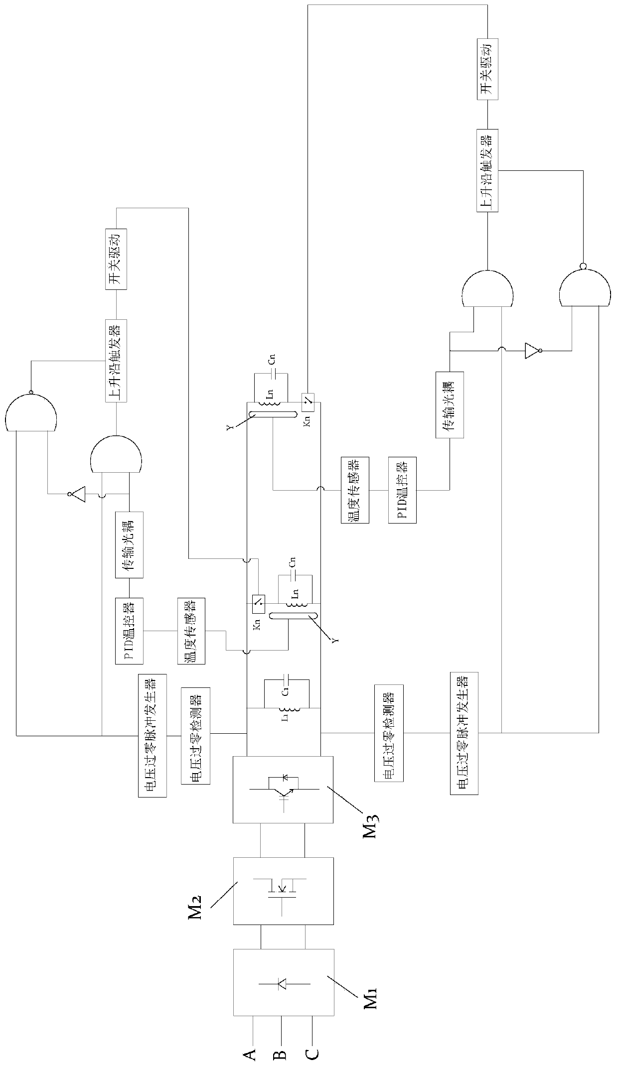
[0039] see figure 1 As shown, the present invention provides a multi-station induction heating circuit, the circuit includes a power converter, the power converter includes a rectification module M1, a voltage regulation module M2 and an inverter module M3, a rectification module M1, a voltage regulation module M2 It is connected with the inverter module M3 in sequence, and the input end of the rectification module M1 is connected with an external three-phase network voltage; the output end of the in...


PUM


Abstract

The invention discloses a multi-station induction heating circuit. The circuit comprises a power source converter; the input end of the power source converter is connected with an external three-phasenetwork voltage; a sine alternating-current voltage of which the power source converter frequency is f is outputted from two output ends of the power source converter; the circuit also comprises a heater; the heater comprises at least one heating module; each heating module comprises a heating inductor and a resonant capacitor; the heating inductor and the resonant capacitor are connected in parallel; one common end of the heating inductor and the resonant capacitor is connected with one output end of the power source converter; the other common end of the heating inductor and the resonant capacitor is connected with the other output end of the power source converter in a time-sharing manner; and the heater has a total natural resonance frequency f0, and the circuit maintains a state thatf is equal to f0 in a working process. Based on the heating circuit, the invention further provides a working method and a control method of the heating circuit. The heating circuit provided by the invention is simple in architecture and small in equipment size. With the heating circuit adopted, the problem of interference between heaters arranged on different stations is solved; and a good heating effect can be achieved.

Description

technical field [0001] The invention belongs to the technical field of induction heating, and in particular relates to an induction heating control circuit and a control method thereof. Background technique [0002] In the process of mechanical manufacturing, the same workpiece is usually produced in large quantities. When using induction heating technology to heat the same batch of workpieces with the same shape and the same size, it is often necessary to set up multiple stations. [0003] For example, a multi-station tempering induction heating device is disclosed in the patent application number "200820056447.0", which includes several induction heating coils, power output busbars, connecting copper bars and insulating backing plates, and the power output One end of the busbar is connected to the external power supply, the other end of the power output busbar is connected to the induction heating coil, and the connection between the power output busbar and the induction h...

Claims


Application Information

Patent Timeline
Patent Type & Authority Applications(China)
IPC IPC(8): H05B6/06
CPCH05B6/06
Inventor 韦伟平雷丽萍雷剑利
Owner 深圳市双平电源技术有限公司
Why Eureka
Try Eureka