Reactive power compensation method, device and equipment
A compensation device and compensation method technology, applied in reactive power compensation, reactive power adjustment/elimination/compensation, etc., can solve problems such as voltage fluctuations, achieve the effects of reducing control costs, solving voltage fluctuations, and suppressing voltage fluctuations exceeding the standard
- Summary
- Abstract
- Description
- Claims
- Application Information
AI Technical Summary
Problems solved by technology
Method used
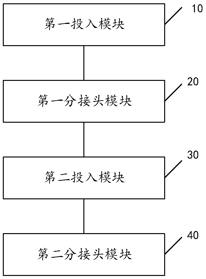
Image

Examples
Embodiment Construction
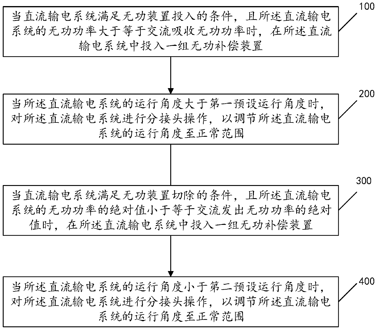
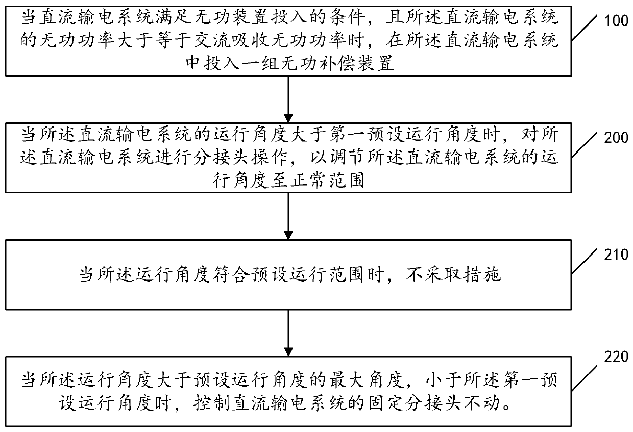
[0039] In order to enable those skilled in the art to better understand the solution of the present application, the technical solution in the embodiment of the application will be clearly and completely described below in conjunction with the accompanying drawings in the embodiment of the application. Obviously, the described embodiment is only It is a part of the embodiments of this application, not all of them. Based on the embodiments in this application, all other embodiments obtained by persons of ordinary skill in the art without making creative efforts belong to the scope of protection of this application.
[0040] In some cases, due to the limitation of equipment manufacturing capacity, the voltage fluctuation caused by the first tap of the converter transformer cannot be too large, and the control voltage fluctuation will greatly limit the group capacity of the reactive power compensation device. However, the limited group capacity of the reactive power compensation ...
PUM
 Abstract
Description
Claims
Application Information
 - R&D
- Intellectual Property
- Life Sciences
- Materials
- Tech Scout
- Unparalleled Data Quality
- Higher Quality Content
- 60% Fewer Hallucinations
Browse by: Latest US Patents, China's latest patents, Technical Efficacy Thesaurus, Application Domain, Technology Topic, Popular Technical Reports.
© 2025 PatSnap. All rights reserved.Legal|Privacy policy|Modern Slavery Act Transparency Statement|Sitemap|About US| Contact US: help@patsnap.com