
Clamping and manufacturing equipment capable of reducing compression deformation degree of spectacle frame body

A technology for the degree of deformation and manufacturing equipment, which is applied in the field of clamping and polishing of eyeglass frames, and can solve the problems of poor rigidity, inability to be polished at bends, and small clamping adjustment range of the clamping mechanism.

Active Publication Date: 2020-01-17
瑞安市联胜科技有限公司
View PDF11 Cites 1 Cited by
  • Summary
  • Abstract
  • Description
  • Claims
  • Application Information

AI Technical Summary

Problems solved by technology

[0004] Although the traditional polishing equipment can polish the spectacle frame well, but because the frame is metal and the rigidity is poor, if the clamping force of the clamping mechanism is not properly controlled, it will leave pinch marks on the surface of the frame, and the traditional The clamping mechanism has a small clamping adjustment range and cannot adapt to various shapes of spectacle frames. In addition, traditional grinding equipment needs to be rotated at multiple angles to complete the grinding of each part of the frame, and there are many bends in the frame. , and the rotation angle of the grinding equipment is limited, which results in partial bending that cannot be polished, which affects the painting effect of the frame in the later stage. Therefore, a clamping manufacturing equipment that reduces the degree of compression deformation of the spectacle frame came into being.

Method used


Image

  • Clamping and manufacturing equipment capable of reducing compression deformation degree of spectacle frame body
  • Clamping and manufacturing equipment capable of reducing compression deformation degree of spectacle frame body
  • Clamping and manufacturing equipment capable of reducing compression deformation degree of spectacle frame body

Examples


Embodiment Construction

[0023] The following will clearly and completely describe the technical solutions in the embodiments of the present invention with reference to the accompanying drawings in the embodiments of the present invention. Obviously, the described embodiments are only some, not all, embodiments of the present invention. Based on the embodiments of the present invention, all other embodiments obtained by persons of ordinary skill in the art without making creative efforts belong to the protection scope of the present invention.

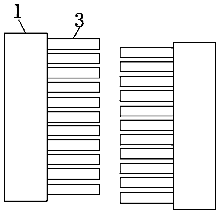
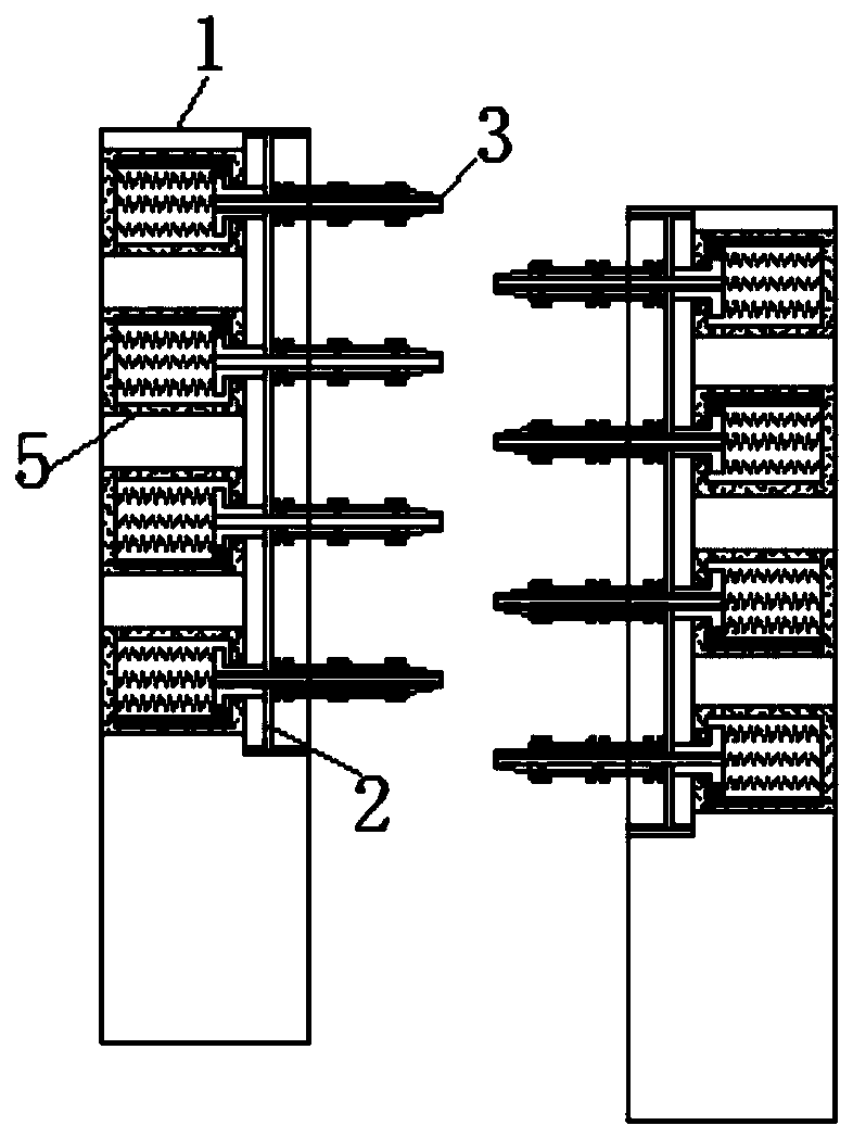
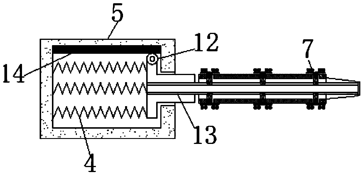
[0024] see Figure 1-6 , a clamping manufacturing device for reducing the degree of compression deformation of the spectacle frame body, including a housing 1, the number of the housing 1 is two, and they are symmetrically staggered, and the squeezed and unsqueezed support rods 3 will meet The spectacle frame forms a clamping force, which facilitates the formation of a clamping force on the spectacle frame. The spectacle frame to be polished is placed between ...


PUM


Abstract

The invention relates to the technical field of spectacle frame body clamping and polishing, and discloses clamping and manufacturing equipment capable of reducing the compression deformation degree of a spectacle frame body. The equipment comprises shells, sliding plates are slidably connected with the interiors of the shells, supporting rods are movably connected to the surfaces of the sliding plates, reset springs are movably connected to the sides, close to the shells, of the supporting rods, and impurity storage boxes are fixedly connected to the ends, away from the supporting rods, of the reset springs. Inlets and outlets are formed in the surfaces of the supporting rods, and folding plates are movably connected to the surfaces of the inlets and outlets. When the folding plates are folded in half, telescopic pieces can be extruded, so that the telescopic pieces extrude elastic plates and are retracted, the supporting plates are finally pushed into the shells, and the part, not incontact with the spectacle frame body, of the supporting rods can be kept still. The symmetric shells are staggered, and the extruded and non-extruded supporting rods form clamping force on the spectacle frame body, so that the effect of clamping the surface of the spectacle frame body without clamping marks is achieved.

Description

technical field [0001] The invention relates to the technical field of clamping and polishing of spectacle frames, in particular to clamping manufacturing equipment for reducing the compression deformation of spectacle frames. Background technique [0002] Glasses are composed of frames and lenses, which are worn in front of the eyes of the human body to improve vision, protect eyes, or be used for decoration; a complete pair of glasses requires multi-step manufacturing to complete, and the clamping and polishing of the glasses frame is relatively difficult. important. [0003] Spectacle frames are divided into metal and plastic materials. Metal spectacle frames need to be polished after being cut and formed. Traditional polishing equipment clamps and fixes the spectacle frames, and polishes them with grinding equipment. [0004] Although the traditional polishing equipment can polish the spectacle frame well, but because the frame is metal and the rigidity is poor, if the ...

Claims


Application Information

Patent Timeline
Patent Type & Authority Applications(China)
IPC IPC(8): B24B19/00B24B27/00B24B41/00B24B41/06B24B47/00B24B47/12
CPCB24B19/00B24B27/0076B24B41/00B24B41/06B24B47/00B24B47/12
Inventor 袁长干
Owner 瑞安市联胜科技有限公司
Learn More