
Display

A display and filter technology, applied in the field of displays with the following pixels

Active Publication Date: 2020-02-04
E INK CORPORATION
View PDF10 Cites 0 Cited by
  • Summary
  • Abstract
  • Description
  • Claims
  • Application Information

AI Technical Summary

Problems solved by technology

However, it is challenging to configure PCM-based pixels so that they can also provide the full range of black and gray levels required for full-color displays.

Method used


Image

  • Display
  • Display
  • Display

Examples


Embodiment Construction

[0023] Throughout the specification, the terms "optical" and "light" are used as they are commonly used terms in the art in relation to electromagnetic radiation, but it is understood that they are not limited to visible light in the context of this specification. It is contemplated that the invention may also be used at wavelengths outside the visible spectrum, such as infrared and ultraviolet light.

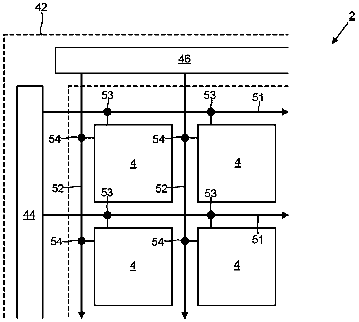
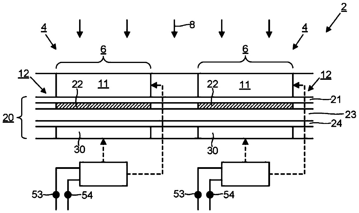
[0024] figure 1 and figure 2 Driving electronics 2 for a part of the display are shown. The display includes a plurality of pixels 4 . figure 1 Four example pixels 4 in the upper left corner of the display are shown in . Each pixel 4 includes a first optical element 11 and a second optical element 12 (such as figure 2 shown). The first optical element 11 is reversibly switchable between at least two optical states. The second optical element 12 is reversibly switchable between at least two optical states. Viewed from the viewing side of the display (for example, along ...


PUM


Abstract

The disclosure relates to displays. In one arrangement a plurality of pixels are provided. Each pixel comprises a first optical element reversibly switchable between at least two optical states, and asecond optical element reversibly switchable between at least two optical states. The first optical element overlaps spatially with the second optical element in an overlap region when viewed from aviewing side of the display, such that an overall optical effect for the overlap region is defined by a combination of the optical state of the first optical element and the optical state of the second optical element. Row signal lines and column signal lines allow individual addressing of each pixel by applying a combination of a row control signal and a column control signal to the pixel. A driving controller applies the row control signals and the column control signals to the pixels. For each pixel, the same row signal line and column signal line can be used to switch the first optical element and the second optical element independently of each other.

Description

technical field [0001] The present invention relates to a display in which individual pixels can be efficiently switched, and more particularly to a display having pixels that use a Phase Change Material (PCM) to control color and a separate optical shutter to Controls the gray scale. Background technique [0002] The use of PCMs in high resolution reflective and see-through displays is known. PCMs are materials that can be switched between multiple phases with different optoelectronic properties electrically, optically or thermally. Bistable PCMs are particularly attractive because, after the phase transition has been completed, no continuous application of power is required to maintain the new state. PCM optoelectronic devices can dynamically change their optical properties by initiating a phase transition in the PCM using a rapid pulse of thermal energy (provided by any means, such as electrically or optically). Pixels can be switched on micron-scale areas to achieve h...

Claims


Application Information

Patent Timeline
IPC IPC(8): G09G3/20G02F1/1335
CPCG02F1/133514G09G3/2003G09G3/3433G09G3/3648G09G2300/023G09G2300/0426G09G2300/0452G09G2300/0804G09G2310/0202G02F1/0147G02F2201/44
Inventor 塞尔希奥·卡斯蒂略·加西亚本·布劳顿培曼·胡赛尼克莱梅特·塔拉格兰德
Owner E INK CORPORATION
Learn More