Display module and display device

A display module and display panel technology, which is applied in the directions of identification devices, character and pattern recognition, instruments, etc., and can solve the problem of not being able to see the display screen

Active Publication Date: 2020-02-07
BOE TECH GRP CO LTD
View PDF9 Cites 5 Cited by
  • Summary
  • Abstract
  • Description
  • Claims
  • Application Information

AI Technical Summary

Problems solved by technology

[0003] In view of this, an embodiment of the present invention provides a display module and a display device to solve the existing problem of not being able to see the picture on the display screen caused by wearing polarized sunglasses

Method used


Image

  • Display module and display device
  • Display module and display device
  • Display module and display device

Examples


Embodiment 1

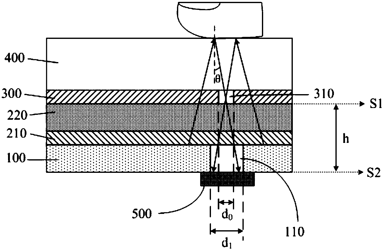
[0041] Generally, in order to protect the device, in the specific implementation, in the embodiment of the present invention, such as figure 2 As shown, the display module may further include a protective cover 400 disposed on a side of the second 1 / 4λ wave plate 300 away from the display panel 100 . In specific implementation, in the embodiment of the present invention, such as figure 2 As shown, the second 1 / 4λ wave plate 300 may include a plurality of first through holes 310 for realizing pinhole imaging. The display area of ​​the display panel may include: a transparent area 110 corresponding to each first through hole 310; the orthographic projection of the transparent area 110 on the display panel 100 has an intersection overlapping area. The display module may further include: a photosensitive detector 500 for receiving an image formed by the fingerprint passing through the first through hole 310 . Further, in order to improve the precision of the pinhole imaging, ...

Embodiment 2

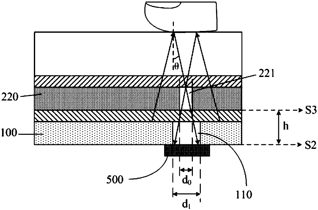
[0053] The structural diagram of the display module corresponding to this embodiment is as follows image 3 As shown, it is modified for the implementation of the first through hole in the first embodiment. The following only describes the differences between this embodiment and the first embodiment, and the similarities will not be repeated here.

[0054] In specific implementation, in the embodiment of the present invention, such as image 3 As shown, the linear polarizer 220 may include a plurality of first through holes 221 for realizing pinhole imaging. The display area of ​​the display panel may further include: a transparent area 110 corresponding to each first through hole 221; the orthographic projection of the transparent area 110 on the display panel 100 and the orthographic projection of the corresponding first through hole 221 on the display panel 100 have overlapping areas. Moreover, the display module may further include: a photodetector 500 for receiving an ...

Embodiment 3

[0059] The structural diagram of the display module corresponding to this embodiment is as follows Figure 4 As shown, it is modified for the implementation of the first through hole in the first embodiment. The following only describes the differences between this embodiment and the first embodiment, and the similarities will not be repeated here.

[0060] In specific implementation, in the embodiment of the present invention, such as Figure 4As shown, the second 1 / 4λ wave plate 300 and the linear polarizing plate 220 include a plurality of first through holes 320 for realizing pinhole imaging. The display area of ​​the display panel may further include: a transparent area 110 corresponding to each first through hole 320; the orthographic projection of the transparent area 110 on the display panel 100 and the orthographic projection of the corresponding first through hole 320 on the display panel 100 have overlapping areas. Moreover, the display module may further include...


PUM

PropertyMeasurementUnit
diameteraaaaaaaaaa

Abstract

The invention discloses a display module and a display device; a second 1/4 lambda wave plate is arranged on the side, deviating from a display panel, of a linearly polarizing film, the light emittedby the display panel becomes linearly polarized light after passing through the first 1/4 lambda wave plate and the linearly polarizing film, and the linearly polarized light is converted into circularly polarized light after passing through the second 1/4 lambda wave plate. Thus, when polarized sunglasses are worn by a person, whether the absorption axis of the polarized sunglasses is in the horizontal direction or in the vertical direction, light is always transmitted into the human eyes through the polarized sunglasses, so that an observer can see the pictures displayed by the display panel.

Description

technical field [0001] The invention relates to the field of display technology, in particular to a display module and a display device. Background technique [0002] At present, a circular polarizer is generally arranged on the light emitting side of the display screen of an electronic device, so that the light passing through the circular polarizer is linearly polarized light. However, polarized sunglasses currently on the market are equivalent to linear polarizers, and their absorption axes are horizontal (ie 0°) or vertical (ie 90°). When the polarization direction of the light passing through the circular polarizer is parallel to the absorption axis of the polarizing sunglasses, the light passing through the circular polarizing film will be absorbed by the polarizing sunglasses, causing the human eye to be unable to see the light, which in turn leads to inability to Seeing the picture on the display screen, thus greatly degrading the user experience. Contents of the ...

Claims


Application Information

Patent Timeline
Patent Type & Authority Applications(China)
IPC IPC(8): G09F9/33G09F9/30
CPCG09F9/33G09F9/301G09F9/30G02B5/30G06V40/1318H10K59/65H10K59/00H10K50/86H10K59/131
Inventor 孙艳六
Owner BOE TECH GRP CO LTD
Why Eureka
Try Eureka