
Electronic product outer shell as well as electronic product cover plate spraying method and spraying device

A technology for electronic products and spraying equipment, applied in coatings, spray booths, spraying devices, etc., can solve the problems of low spraying efficiency, dirt and gaps, low ink utilization, etc., to improve spraying efficiency and small film thickness error , The effect of uniform ink output

Active Publication Date: 2020-02-21
BYD CO LTD
View PDF6 Cites 2 Cited by
  • Summary
  • Abstract
  • Description
  • Claims
  • Application Information

AI Technical Summary

Problems solved by technology

[0003] In the existing spraying method, the glass cover plate is fixed on the spraying fixture, and the spray gun sprays the surface of the glass cover plate fixed on the fixture along the X and Y travel paths. However, when the ink is atomized, the spray gun itself is still Due to the speed of movement, it is very easy to cause flying oil, and it is necessary to increase the repair process in the later stage, which is time-consuming and laborious, and is easy to cause defects such as scratches, light transmission, dirt, and gaps; the atomization of the spray gun ink cannot fully cover the upper surface of the glass cover, resulting in The glass cover plate after spraying is prone to defects such as edge penetration; in addition, the film thickness error on the glass cover plate after painting is relatively large, which cannot meet the industry standard. The spraying efficiency of the existing spraying method is low, the utilization rate of ink is low, and it cannot Realize the assembly line and batch spraying of glass cover plate

Method used


Image

  • Electronic product outer shell as well as electronic product cover plate spraying method and spraying device
  • Electronic product outer shell as well as electronic product cover plate spraying method and spraying device
  • Electronic product outer shell as well as electronic product cover plate spraying method and spraying device

Examples


Embodiment Construction

[0039] Specific embodiments of the present disclosure will be described in detail below in conjunction with the accompanying drawings. It should be understood that the specific embodiments described here are only used to illustrate and explain the present disclosure, and are not intended to limit the present disclosure.

[0040] In this disclosure, unless stated otherwise, the used orientation words such as "upper" and "lower" usually refer to the definition under the normal use of the electronic product cover plate spraying equipment provided by this disclosure. For details, please refer to Figure 7 to Figure 9 In the directions shown in the drawings, "inside" and "outside" refer to the inside and outside of the contour of the corresponding component, and "front" and "back" refer to the conveying direction of the electronic product cover, for example Figure 4 in the direction of the arrow shown in . In addition, when the following description refers to the accompanying dra...


PUM


Abstract

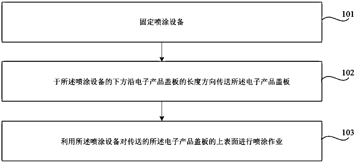
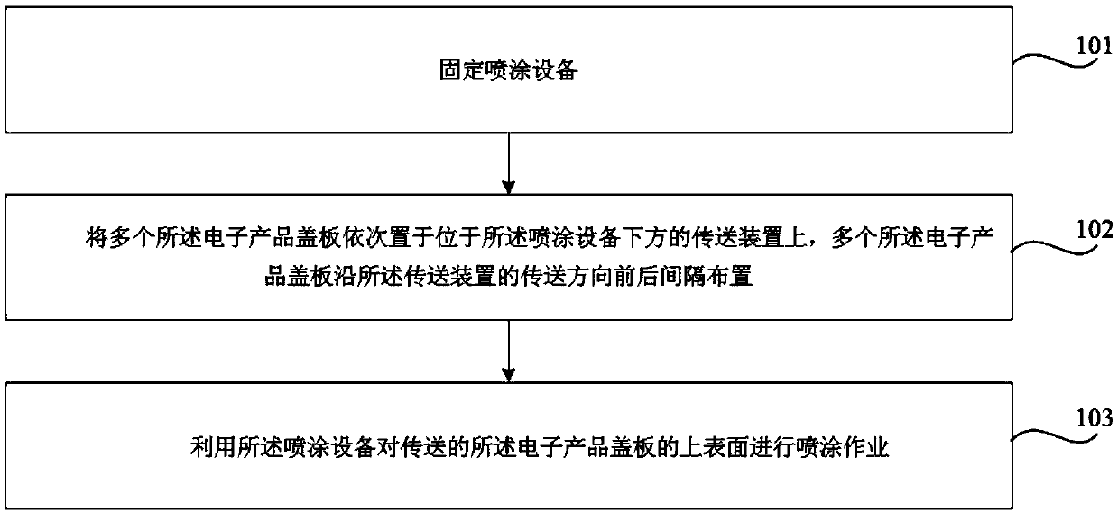
The invention relates to an electronic product outer shell as well as an electronic product cover plate spraying method and spraying device. The spraying method involves a fixing spraying device, andan electronic product cover plate is conveyed in the length direction of the electronic product cover plate below the spraying device; and the method comprises performing spraying operation on the upper surface of the conveyed electronic product cover plate through using the spraying device, and during the step of performing spraying operation on the upper surface of the conveyed electronic product cover plate through using the spraying device, the effective spraying width of the spraying device is larger than the width of the electronic product cover plate. In this way, the spraying device isfixed, and the electronic product cover plate is conveyed below the spraying device for being subjected to spraying operation, assembly line type and batch quantitative operation can be achieved, thespraying efficiency is improved; and meanwhile, the effective spraying width of the spraying device is far larger than the width of the electronic product cover plate, and the effective area of ink atomization completely coats the electronic product cover plate, so that full-covering type spraying of the electronic product cover plate is achieved.

Description

technical field [0001] The present disclosure relates to the field of production and manufacturing of electronic products, and in particular, relates to a spraying method and spraying equipment for an electronic product casing, an electronic product cover plate. Background technique [0002] During the manufacturing process of electronic products, such as mobile phones and tablets, etc., cover plates are usually installed to protect the electronic components inside. Take the glass cover on the mobile phone shell as an example. Since the glass cover is made of transparent material, in order to prevent the human eye from seeing the electronic components inside the mobile phone through the glass cover, the surface of the glass cover will be sprayed to protect the glass cover. board and enhance the aesthetics of the phone. [0003] In the existing spraying method, the glass cover plate is fixed on the spraying fixture, and the spray gun sprays the surface of the glass cover pla...

Claims


Application Information

Patent Timeline
Patent Type & Authority Applications(China)
IPC IPC(8): B05B13/02B05B16/00B05D1/02
CPCB05B13/0221B05B16/00B05D1/02
Inventor 蒋长坚黄起明段水亮
Owner BYD CO LTD
Learn More