Long range barcode scanning through conversion of coherent light

A technology of coherent light and incoherent light, applied in the improvement field of scanning barcodes or other patterns, can solve insurmountable and complicated problems

Pending Publication Date: 2020-02-21
VIRTEK VISION INT ULC
View PDF1 Cites 0 Cited by
  • Summary
  • Abstract
  • Description
  • Claims
  • Application Information

AI Technical Summary

Problems solved by technology

This problem is only compounded when trying to scan over long distances
Problems related to laser spots cannot be overcome even with integrated high-precision cameras

Method used


Image

  • Long range barcode scanning through conversion of coherent light
  • Long range barcode scanning through conversion of coherent light
  • Long range barcode scanning through conversion of coherent light

Examples


Embodiment Construction

[0023] The method of the present invention provides the operator with the ability to scan barcodes, QR logos, etc. at distances significantly greater than required by current short range barcode scanners. Generating coherent light illumination and then converting the coherent incident light to incoherent light overcomes problems associated with, for example, laser spot (which therefore requires the scanner to be in close proximity to barcodes, QR signs, etc.).

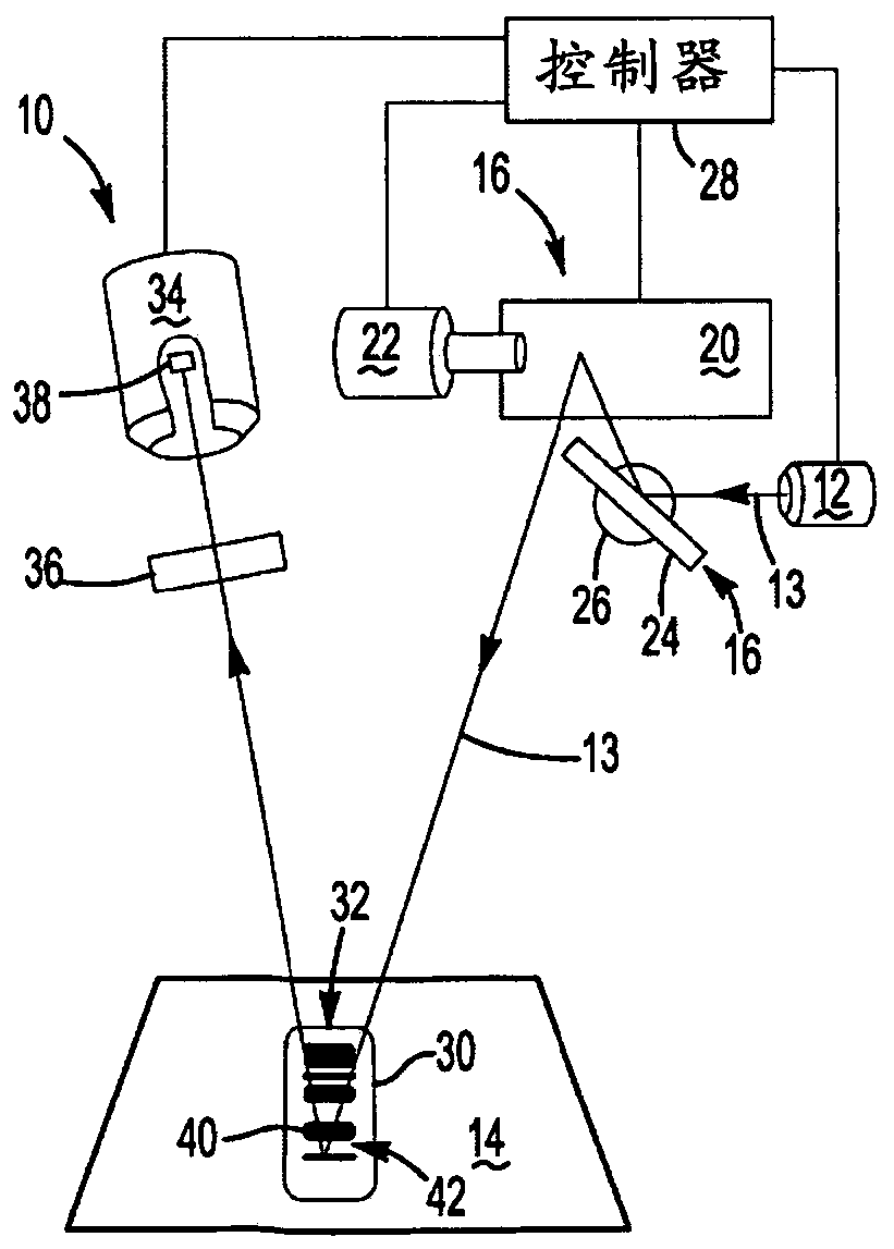
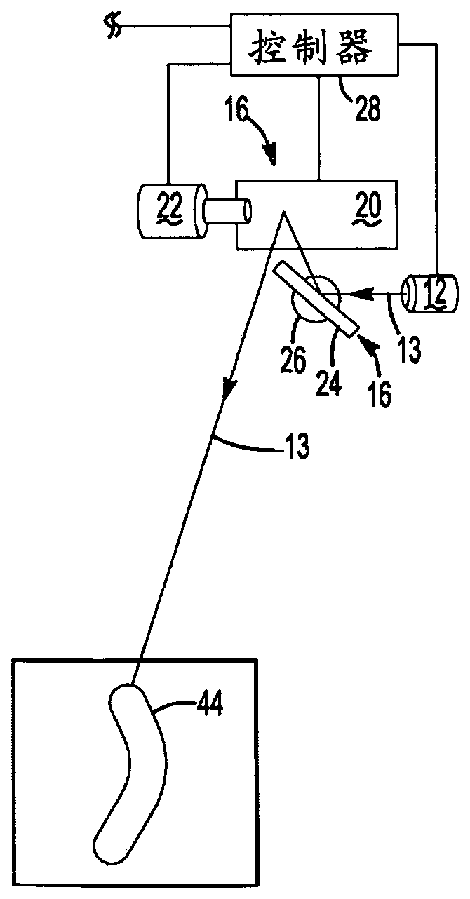
[0024] now refer to figure 2 , an assembly for carrying out the method of the invention is indicated generally at 10 . The assembly includes a laser projector 12 for generating a laser beam 13 . A laser beam 13 is directed towards a working surface 14 via a first galvanometer 16 and a second galvanometer 18 . The first oscillating mirror 16 includes a first reflecting element 20 driven by a first scanning motor 22 , and the second oscillating mirror 18 includes a second reflecting element 24 including a second scann...


PUM

PropertyMeasurementUnit
Wavelengthaaaaaaaaaa

Abstract

The invention discloses long range barcode scanning through conversion of coherent light. A method of optically scanning indicia on an object includes providing a coherent light source for illuminating the object with coherent light. The object is marked with indicia including a first feature and a second feature, with the first feature including reflection of coherent light and said second feature including emittance of non-coherent light when illuminated. An imaging device is capable of distinguishing coherent light from non-coherent light. The indicia are illuminated with coherent light generated by the coherent light source causing the indicia to reflect coherent light and emit non-coherent light. The coherent light is distinguished from the non-coherent light emitted from the indiciaby a controller for identifying a pattern of one of said first feature and said second feature.

Description

[0001] Cross References to Related Applications [0002] This application claims priority to U.S. Provisional Patent Application No. 62 / 717,431, filed August 10, 2018, the contents of which are incorporated herein by reference. technical field [0003] The present invention generally relates to improved methods for scanning barcodes or other patterns. More specifically, it relates to a method of distinguishing or blocking reflections of coherent light from incoherent emissions of barcodes and other patterns illuminated by a coherent light source capable of scanning barcodes and other patterns at increased offset distances. Background technique [0004] In recent years, the use of markings (coded markings) in the form of barcodes and QR markings has increased rapidly in manufacturing environments where markings were previously primarily used in the consumer market. This form of marking has been used to identify products or objects to help merchants manage inventory and ident...

Claims


Application Information

Patent Timeline
IPC IPC(8): G06K7/12
CPCG06K7/12G06K7/10554G06K7/10633G06K7/10861G06K7/1092G06K7/10831
Inventor K·D·鲁博
Owner VIRTEK VISION INT ULC
Why Eureka
Try Eureka