
Display panel driving device and configuration method thereof

A driving device and display panel technology, applied to static indicators, instruments, etc., can solve the problems of timing controllers that cannot meet the production requirements, increase the cost and complexity of wiring, and actually use redundant flash memory chips, so as to reduce the number of flash memory chips The effect of reducing the number, simplifying the difficulty of circuit wiring, and improving the utilization rate of storage resources

Active Publication Date: 2020-11-24
TCL CHINA STAR OPTOELECTRONICS TECH CO LTD
View PDF10 Cites 0 Cited by
  • Summary
  • Abstract
  • Description
  • Claims
  • Application Information

AI Technical Summary

Problems solved by technology

[0005] As the size and resolution of liquid crystal display devices increase, the requirements for timing controllers of liquid crystal display devices are also getting higher and higher. For ultra-high-definition 120Hz or 8K 120Hz liquid crystal display devices, a single timing controller is difficult to meet production requirements , for this reason, a technical solution including multiple chip drivers is proposed, that is, multiple timing controllers are set in the liquid crystal display device to work at the same time, and each timing controller corresponds to controlling a corresponding sub-region, that is, each timing controller can only obtain And process the data (such as video data) in its corresponding sub-area, each timing controller is provided with a flash memory chip (Flash), that is, each timing controller is connected with a flash memory chip (such as two timing controllers need two flash memory chip), each timing controller obtains its corresponding drive code (Code) from its corresponding flash memory chip respectively, however, since each timing controller corresponds to a flash memory chip, the number of flash memory chips is too large, and a large amount of time is required Wiring space, and each flash memory chip needs a set of connecting wires, for example, each flash memory chip needs chip select (CS), write protection (WP), input (DI), output (Do) and clock (CLK) five connections A ground wire is needed to connect the timing controller, and a ground wire is needed to connect to the power supply. Too many wires will increase the cost and wiring complexity of the control board (Control Board, CB); and the flash memory chip The actual function is only to store the driver code. When multiple chips are driven, the existence of multiple flash memory chips is redundant in actual use, and the storage resources are not fully utilized. At the same time, each existing timing controller corresponds to a flash memory chip The scheme not only takes up a lot of wiring space, but also increases the wiring cost and wiring complexity, and the resources are also effectively used, which is completely inconsistent with the principle of simple and clear circuit board design.

Method used


Image

  • Display panel driving device and configuration method thereof
  • Display panel driving device and configuration method thereof
  • Display panel driving device and configuration method thereof

Examples


Embodiment Construction

[0046] In order to further illustrate the technical means adopted by the present invention and its effects, the following describes in detail in conjunction with preferred embodiments of the present invention and accompanying drawings.

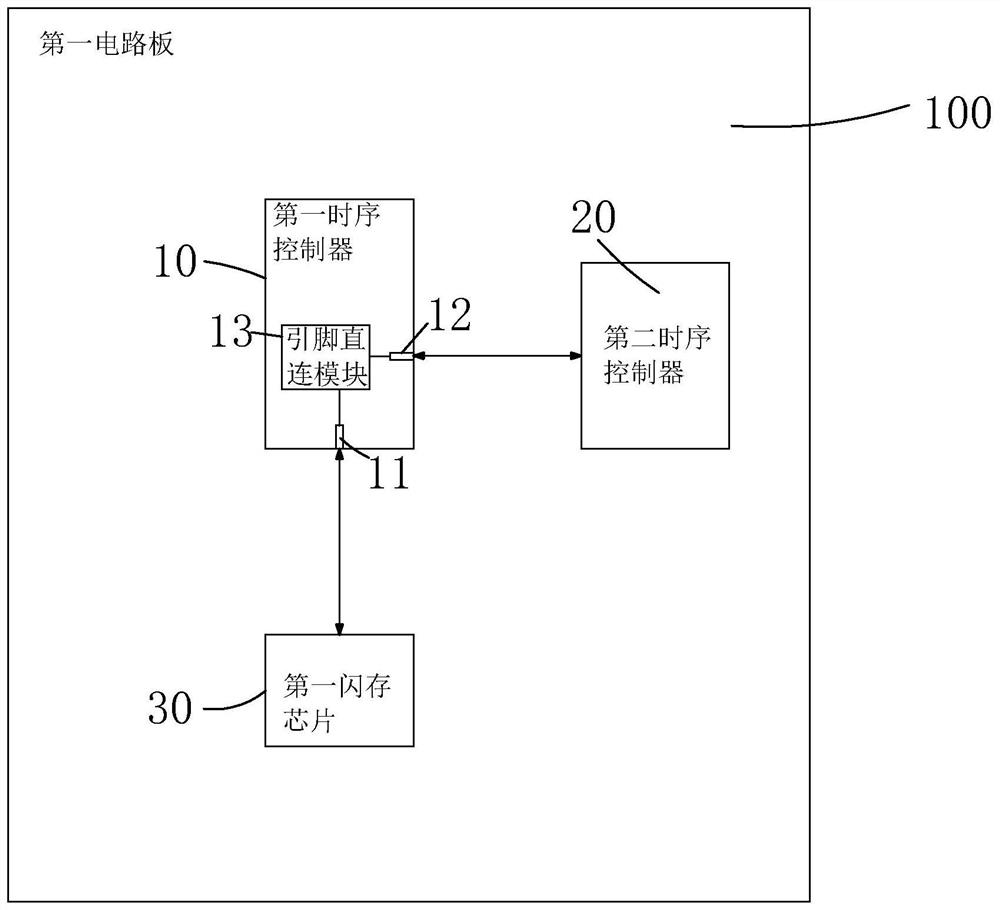
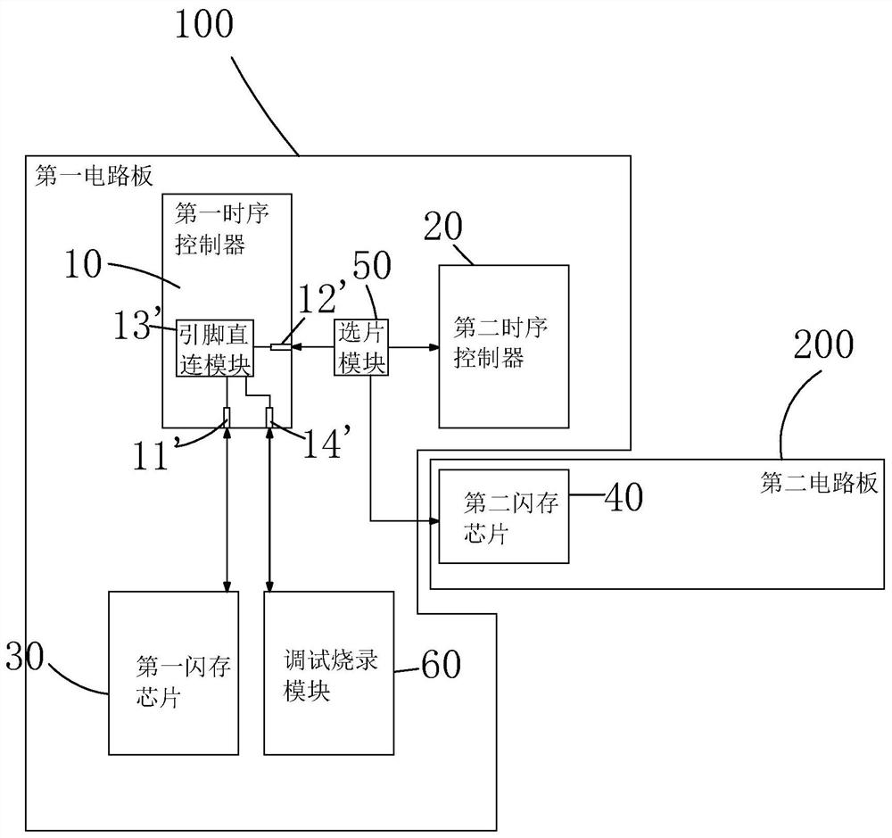
[0047] see figure 1 , the present invention provides a display panel driving device, comprising: a first timing controller 10, a second timing controller 20 connected to the first timing controller 10, and a second timing controller connected to the first timing controller 10 A flash memory chip 30;

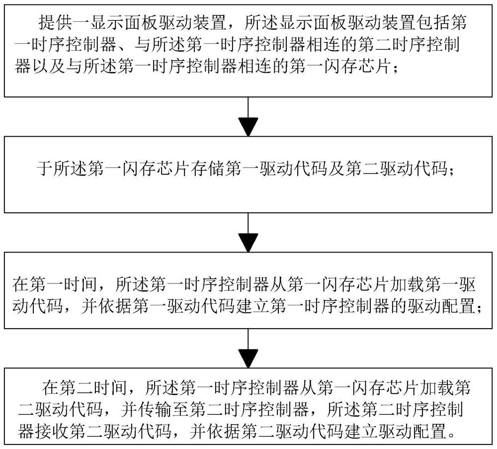
[0048] The first flash memory chip 30 is used to store the first driving code and the second driving code;

[0049] The first timing controller 10 is used to load the first driving code from the first flash memory chip 30 at the first time, and establish the driving configuration according to the first driving code, and load the second driving code from the first flash memory chip 30 at the second time. Drive the code and transmit it to the sec...


PUM


Abstract

The invention provides a display panel driving device and a configuration method thereof. The display panel driving device includes: a first timing controller, a second timing controller connected to the first timing controller, and a first flash memory chip connected to the first timing controller; the first flash memory chip is used to store the first The driving code and the second driving code; the first timing controller is used to load the first driving code from the first flash memory chip at the first time, and establish the driving configuration according to the first driving code, and load the first driving code from the first flash memory chip at the second time The second driving code is transmitted to the second timing controller; the second timing controller is used to receive the second driving code and establish the driving configuration according to the second driving code, which can realize the configuration of two timing controllers through one flash memory chip , can reduce the number of flash memory chips, simplify the difficulty of circuit wiring, reduce product costs, and improve storage resource utilization.

Description

technical field [0001] The present invention relates to the field of display technology, in particular to a display panel driving device and a configuration method thereof. Background technique [0002] With the development of display technology, liquid crystal displays (Liquid Crystal Display, LCD) and other flat display devices are widely used in mobile phones, televisions, personal Various consumer electronic products such as digital assistants, digital cameras, notebook computers, and desktop computers have become the mainstream of display devices. [0003] Usually, the liquid crystal display panel consists of a color filter substrate (CF, Color Filter), a thin film transistor substrate (TFT, ThinFilm Transistor), a liquid crystal (LC, Liquid Crystal) sandwiched between the color filter substrate and the thin film transistor substrate, and a sealant frame (Sealant )composition. [0004] When the liquid crystal display panel works, it needs to be driven by an external d...

Claims


Application Information

Patent Timeline
Patent Type & Authority Patents(China)
IPC IPC(8): G09G3/36
CPCG09G3/36
Inventor 方晓莉谢剑军
Owner TCL CHINA STAR OPTOELECTRONICS TECH CO LTD
Learn More