

Method for real-time compensation for disturbance force on rotor in magnetic suspension bearing system
A technology of magnetic suspension bearing and real-time compensation, applied in the field of CNC machine tools
- Summary
- Abstract
- Description
- Claims
- Application Information
AI Technical Summary
Problems solved by technology
Method used
Image

Examples
Embodiment Construction
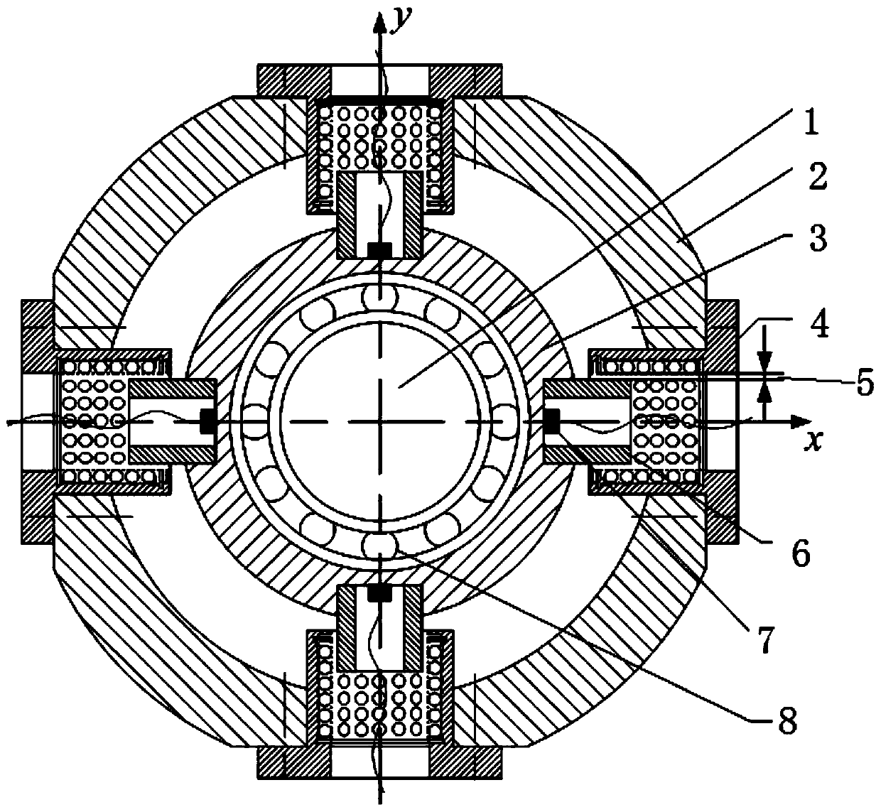
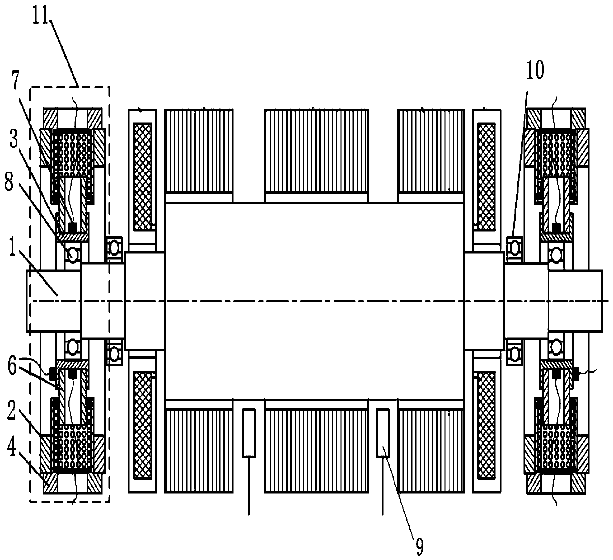
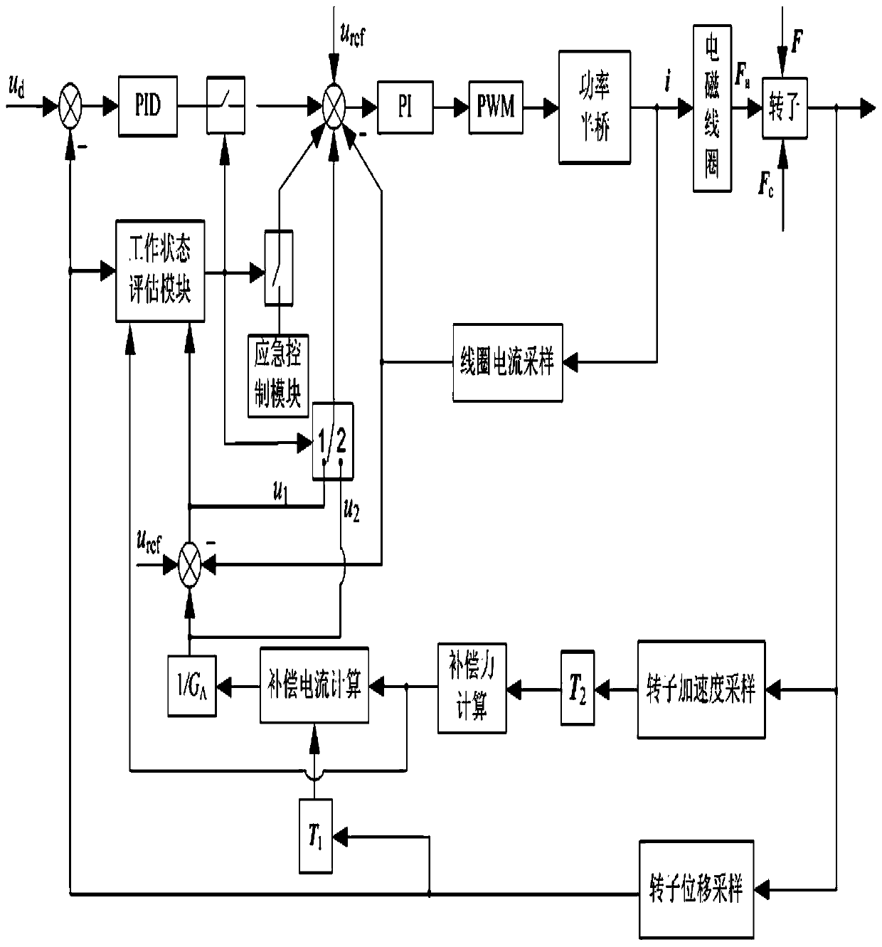
[0027] Such as Figure 1-Figure 4 A method for real-time compensation of the disturbance force suffered by the rotor in the magnetic suspension bearing system includes the following steps:
[0028] Step 1: Install the rotor vibration acceleration online detection device on the rotor of the magnetic suspension bearing system. The rotor vibration acceleration online detection device includes a ball bearing. The inner ring of the ball bearing is fixed on the rotor, and the outer ring of the ball bearing is installed on a bearing seat. The acceleration sensor is arranged on the bearing seat, and the acceleration sensor is used to detect the vibration acceleration of the bearing seat;
[0029] The acceleration sensor indirectly detects the vibration acceleration of the rotor by detecting the vibration acceleration of the bearing seat.
[0030] The ball bearing rotates at a high speed driven by the rotor. Although it does not bear load, it still generates a certain amount of heat. ...
PUM
 Abstract
Description
Claims
Application Information