Placing frame for die steel production

A technology for placing racks and die steel, applied in the field of placing racks, can solve the problems such as the inability to quickly and conveniently replace the drawer plate, increase the labor intensity of the operator, time-consuming and laborious disassembly, etc., so as to save manpower and material resources and reduce the time spent on disassembly. , the effect of simple structure and operation

Inactive Publication Date: 2020-03-06
黄石市华石材料科技有限公司
View PDF0 Cites 0 Cited by
  • Summary
  • Abstract
  • Description
  • Claims
  • Application Information

AI Technical Summary

Problems solved by technology

[0003] The existing rack for die steel production is inconvenient to disassemble if the pumping plate is damaged or contaminated during use, and the pumping plate cannot be replaced quickly and conveniently, which affects work efficiency and delays the follow-up work. Time-consuming and labor-intensive, increasing the labor intensity of the operator

Method used


Image

  • Placing frame for die steel production
  • Placing frame for die steel production
  • Placing frame for die steel production

Examples


Embodiment 1

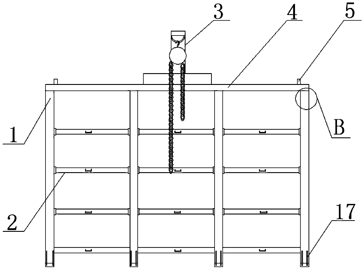
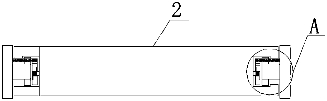
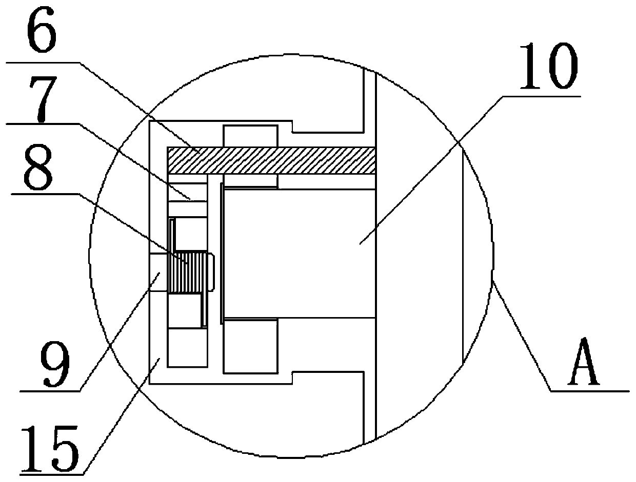
[0023] see Figure 1 to Figure 4 , the present invention provides a technical solution: a placement frame for mold steel production, including a plurality of vertical columns 1, and a plurality of pumping plates 2 are arranged equidistantly between every two columns 1, and the surfaces of the pumping plates 2 are two The side is provided with a second limit groove 15, and the two ends of the pumping plate 2 are fixed with a horizontal plate relative to the surface of the column 1. The surface of the horizontal plate is provided with a roller shaft 10, and the surface of the roller shaft 10 is provided with a roller. The retaining pile 6 is fixed on the surface, and the inner wall of the second limiting groove 15 is provided with a buckle 7 with a ">" cross-section. Through the designed buckle 7, press the upper end of the buckle 7 to bypass the retaining pile 6. The pumping plate 2 is successfully removed without turning the screw, which greatly reduces the time spent on disas...

Embodiment 2

[0025] see Figure 1 to Figure 6 , the present invention provides a technical solution: a placement frame for mold steel production, including a plurality of vertical columns 1, and a plurality of pumping plates 2 are arranged equidistantly between every two columns 1, and the surfaces of the pumping plates 2 are two The side is provided with a second limit groove 15, and the two ends of the pumping plate 2 are fixed with a horizontal plate relative to the surface of the column 1. The surface of the horizontal plate is provided with a roller shaft 10, and the surface of the roller shaft 10 is provided with a roller. The retaining pile 6 is fixed on the surface, and the inner wall of the second limiting groove 15 is provided with a buckle 7 with a ">" cross-section. Through the designed buckle 7, press the upper end of the buckle 7 to bypass the retaining pile 6. The pumping plate 2 is successfully removed without turning the screw, which greatly reduces the time spent on disas...


PUM


Abstract

The invention discloses a placing frame for die steel production. The placing frame for die steel production comprises a plurality of vertical stand columns, wherein a plurality of drawing plates arearranged between every two stand columns at equal distances, second limiting grooves are formed in two sides of the surface of each drawing plate, transverse plates are fixed at two ends of each drawing plate relative to the surface of each stand column, roller shafts are arranged on the surfaces of the transverse plates, and roller wheels are arranged on the surfaces of the roller shafts; throughthe designed buckle, by pressing the upper end of the buckle, the drawing plate can be smoothly taken off bypassing the stop pile without rotating the screw rod, the time spent in disassembly is greatly reduced, manpower and material resources are saved, subsequent production work is conveniently carried out in time, the structure is convenient and simple, operation is easy, practicability is high, and working efficiency is high.

Description

technical field [0001] The invention belongs to the technical field of placement racks, and in particular relates to a placement rack for die steel production. Background technique [0002] The shelf generally refers to the shelf for storing goods, which is a storage device for storing finished items. According to the use, it can be divided into supermarket shelves, storage shelves, and display shelves. Storage shelves are divided into light, medium-sized shelves, heavy-duty shelves, and other categories. [0003] The existing rack for die steel production is inconvenient to disassemble if the pumping plate is damaged or contaminated during use, and the pumping plate cannot be replaced quickly and conveniently, which affects work efficiency and delays the follow-up work. Time-consuming and labor-intensive, increasing the labor intensity of the operator. Contents of the invention [0004] The object of the present invention is to provide a placing frame for mold steel pr...

Claims


Application Information

Patent Timeline
Patent Type & Authority Applications(China)
IPC IPC(8): B25H3/04
CPCB25H3/04
Inventor 余秉治
Owner 黄石市华石材料科技有限公司
Why Eureka
Try Eureka