
Fragmentation device

A component, conveyor technology, applied in the field of glass breaking devices, capable of solving problems such as unsatisfactory, high resistance of window frames, not allowing broken components premature wear contingency plan, etc., to achieve the effect of reducing stress load

Active Publication Date: 2020-03-10
SAINT-GOBAIN GLASS FRANCE
View PDF7 Cites 0 Cited by
  • Summary
  • Abstract
  • Description
  • Claims
  • Application Information

AI Technical Summary

Problems solved by technology

[0005] However, this technical solution is still very unsatisfactory, at least because it requires major adjustments to the conveyor, thus for example precluding the implementation of conveyor belts, and it does not allow contingency against premature wear of fragmented components plan, the knife could potentially strike the window frame which would provide an unusually high resistance

Method used


Image

  • Fragmentation device
  • Fragmentation device
  • Fragmentation device

Examples


Embodiment Construction

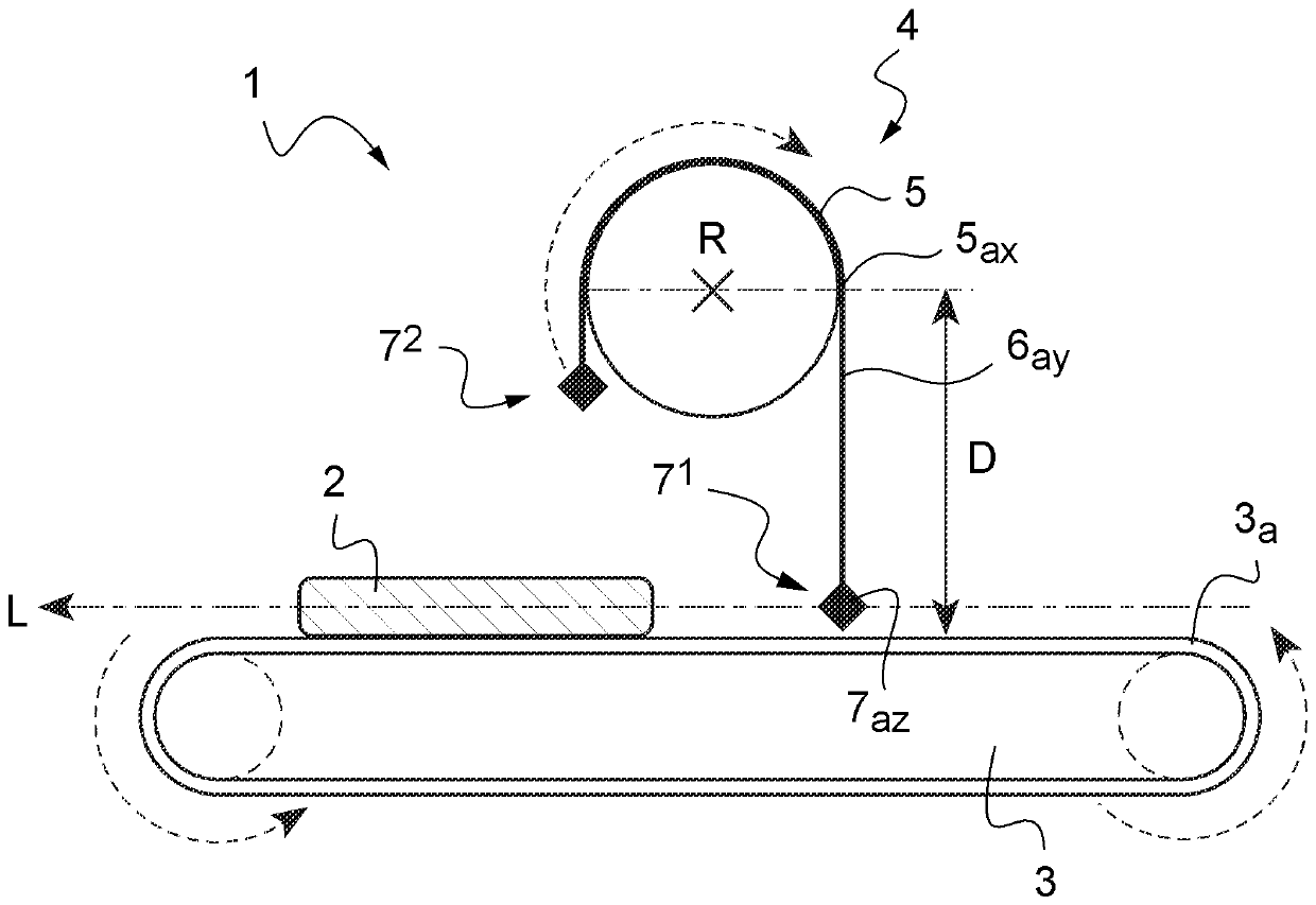
[0054] Such as figure 2 As shown, a breaking device 1 according to a particular embodiment of the invention is designed to break the glass of a used window 2 and comprises:

[0055] - a conveyor 3 designed to convey said window 2 flatly along the longitudinal axis L, and

[0056] - Fragmentation assembly 4, which is located above the conveyor 3 and is designed to fragment the glass of the window 2 as it is conveyed on the conveyor 3.

[0057] More specifically, the fragmentation assembly 4 comprises a roller 5 arranged above the conveyor 3 along an axis of rotation R transverse to the longitudinal axis L.

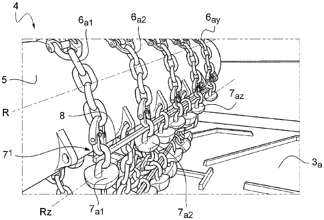
[0058] The drum 5 is connected to the two striker assemblies (7 1 、7 2 ), each impactor assembly 7 1 Consists of a plurality of impact heads (7a1, 7a2, . . . , 7az) designed to impact the conveyor 3 each time the drum 5 rotates.

[0059] For each striker assembly 7 , strike heads ( 7a1 , 7a2 , . . . , 7az ) are aligned in the transverse direction Rz. So, for clarity ...


PUM


Abstract

The invention relates to a device suitable for the fragmentation of the glass of an old window, a corresponding fragmentation method, and the fragmented glass obtained by such a method.

Description

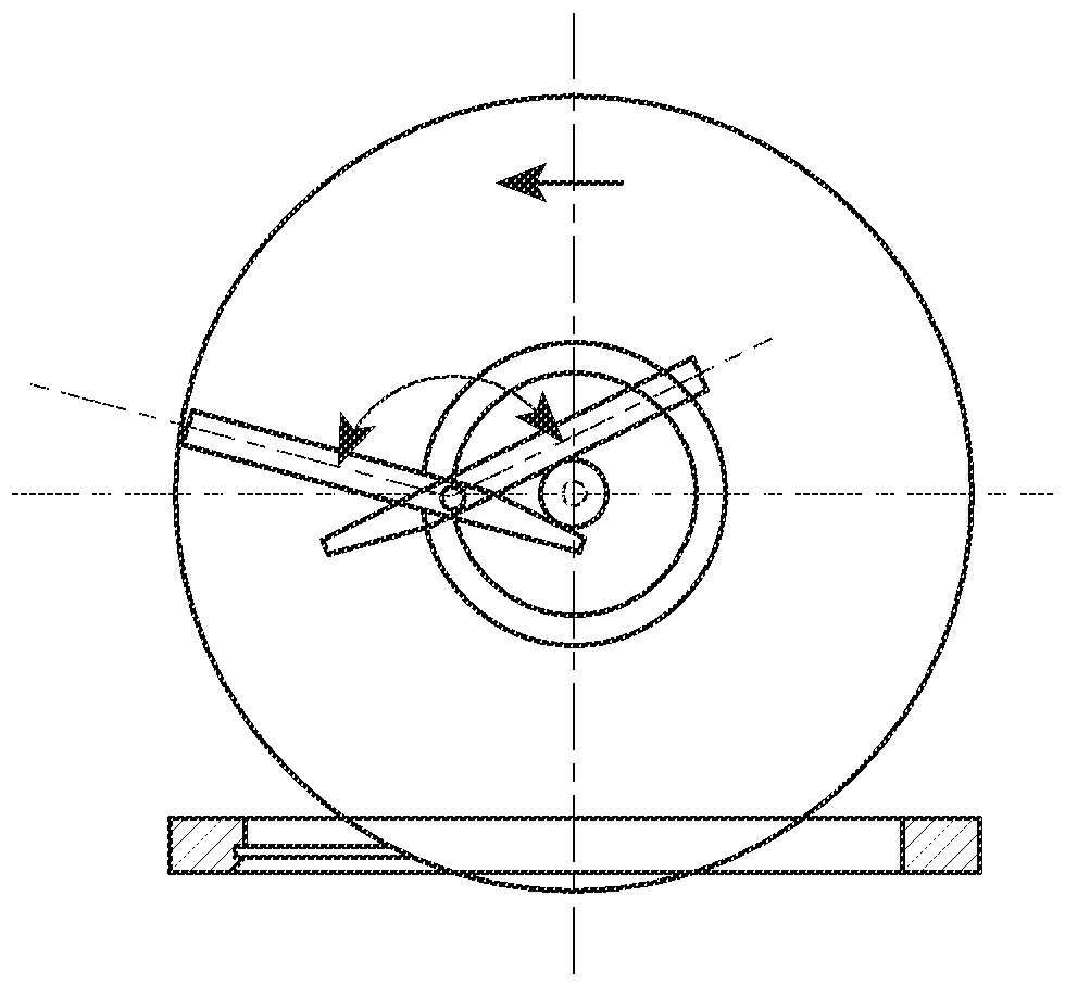
technical field [0001] The invention relates to a device designed to break the glass of used windows, to the corresponding breaking method and to the broken glass obtained using this method. Background technique [0002] Currently, the recycling of used windows is a critical issue, especially in reducing the cost of raw materials from which glass can be made and reducing the environmental impact of new windows. Such recycling entails separating the glass of the used windows from their frames. [0003] From the prior art, including from document EP0618011, a glass-breaking device designed for these purposes is known and comprises: a conveyor adapted to transport used windows flat; and a breaking assembly , a crushing assembly located above the conveyor and adapted to crush the window as it is conveyed on the conveyor. More specifically, and as figure 1 As shown in reference EP0618011, such a fragmentation assembly comprises a plurality of knives arranged to rotate on a dis...

Claims


Application Information

Patent Timeline
Patent Type & Authority Applications(China)
IPC IPC(8): B02C13/16B02C13/28B02C13/286
CPCB02C13/16B02C13/28B02C2013/2816B02C2013/28636
Inventor G.巴伯
Owner SAINT-GOBAIN GLASS FRANCE
Learn More