Supercharge Your Innovation With Domain-Expert AI Agents!

Terminal fitting

A technology of terminal fittings and terminals, which is applied in the direction of contact parts, electrical components, parts of connecting devices, etc., can solve the problems of damage to the usability and increase of terminal fittings

Inactive Publication Date: 2020-03-13
YAZAKI CORP
View PDF6 Cites 0 Cited by
  • Summary
  • Abstract
  • Description
  • Claims
  • Application Information

AI Technical Summary

Problems solved by technology

Meanwhile, if the contact spring is simply made thicker to increase its pressure, the pressure applied to the mating terminal suddenly increases during insertion of the mating terminal into the barrel, which may impair the usability of the terminal fittings

Method used


Image

  • Terminal fitting
  • Terminal fitting
  • Terminal fitting

Examples


Embodiment Construction

[0018] Hereinafter, exemplary embodiments of the present invention will be described in detail with reference to the accompanying drawings.

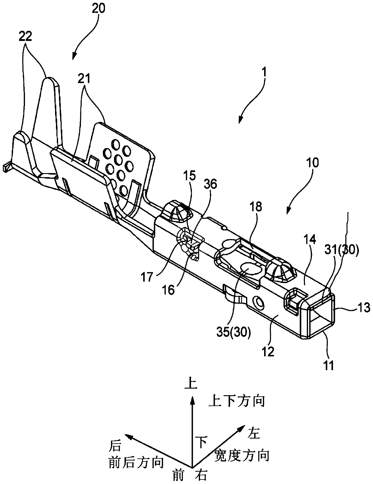
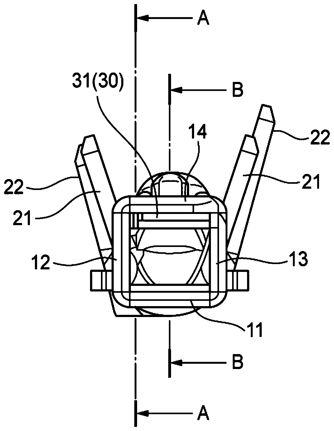
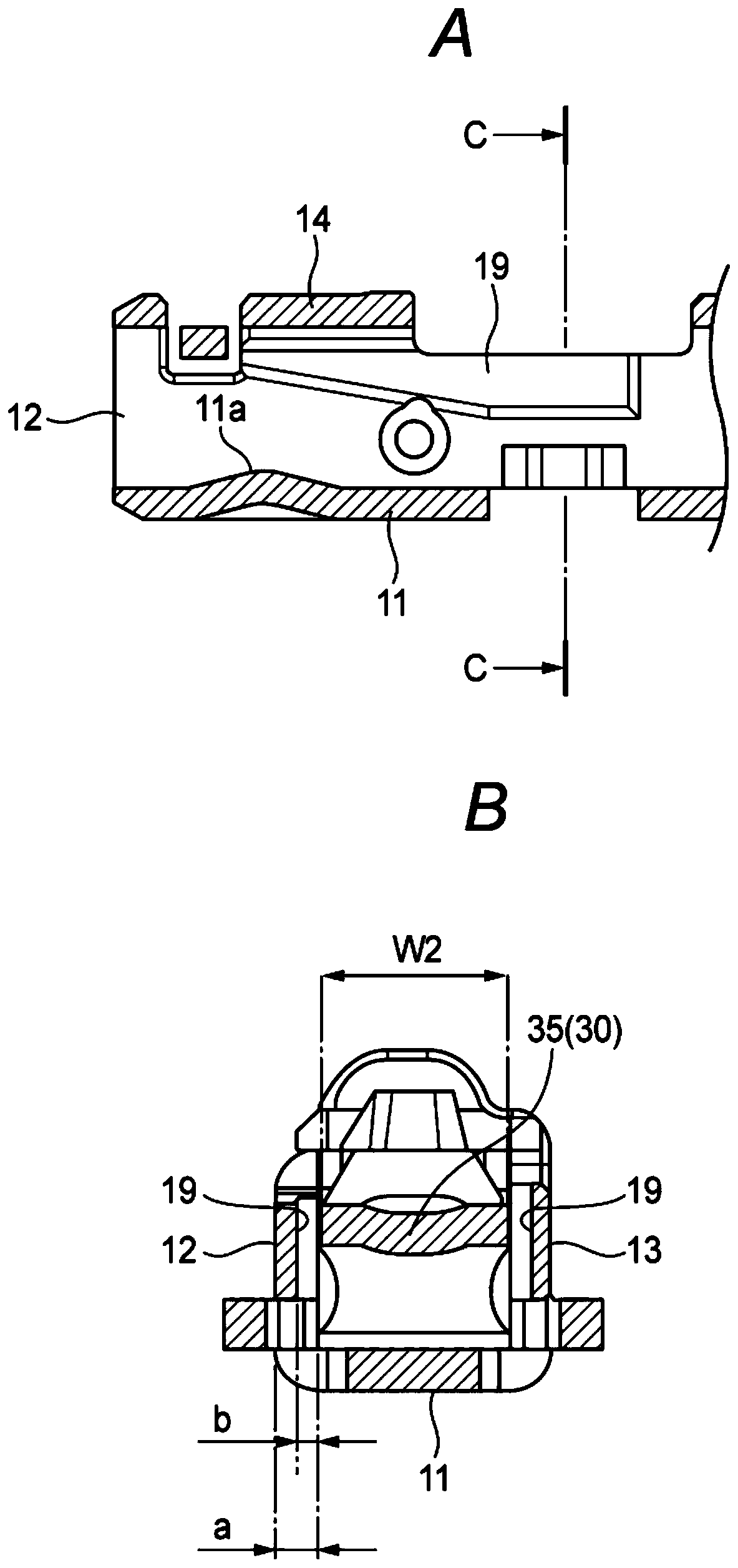
[0019] Such as Figures 1 to 4 As shown in D, the female terminal 1 includes: a cylindrical part 10, a flat mating terminal 40 (hereinafter also referred to as "male terminal", refer to Image 6 A to 6C) are inserted therein; a cylindrical portion 20, which is continuously formed on the rear side of the cylindrical portion 10 and the wire rod is crimped; and a contact beam 30, which is formed inside the cylindrical portion 10 and used for press insertion Male terminal 40. In this embodiment, the female terminal 1 is formed by pressing, bending, etc. one metal plate. In the following, as figure 1 As shown, for the convenience of description, the direction indicators of "front and rear direction", "width direction", "up and down direction", "front", "rear", "left", "right", "upper" and "lower" are used . The "front-rear direction", th...


PUM


Abstract

A terminal fitting including a cylindrical portion into which a mating terminal is to be inserted; and a contact beam provided inside the cylindrical portion, the contact beam extending toward an insertion direction of the mating terminal into the cylindrical portion, being elastically deformable along a deflection direction of the contact beam and including a protruding portion extending in a direction intersecting the deflection direction, and the cylindrical portion including a peripheral wall and an engagement portion to be engaged with the protruding portion to regulate a movement of thecontact beam, the engagement portion including a first portion and a second portion protruding from the peripheral wall of the cylindrical portion toward an inside of the cylindrical portion to regulate the movement of the contact beam in the deflection direction and in the insertion direction respectively.

Description

technical field [0001] The invention relates to a terminal fitting, comprising a cylindrical part inserted into a mating terminal, and a contact beam arranged inside the cylindrical part. Background technique [0002] In the prior art, a terminal fitting (such as a female terminal) is proposed, which includes a cylindrical part inserted into a mating terminal (such as a male terminal) and a cantilever or a contact beam supported on both sides provided inside the cylindrical part (for example, contact springs). Specifically, a terminal fitting in the prior art includes a cantilevered contact spring accommodated in a hollow portion of a cylindrical portion, and a mating terminal inserted into the cylindrical portion is sandwiched between peripheral walls of the cylindrical portion so as to press Contact contact spring. Therefore, for example, during insertion of the mating terminal, an oxide film naturally generated on the surface of the contact spring or the mating terminal...

Claims


Application Information

Patent Timeline
IPC IPC(8): H01R13/11H01R13/02H01R13/629H01R13/52
CPCH01R13/11H01R13/02H01R13/629H01R13/521H01R13/5219H01R13/113H01R4/185H01R4/48185
Inventor 望月惣义松下浩一郎
Owner YAZAKI CORP
Features
  • R&D
  • Intellectual Property
  • Life Sciences
  • Materials
  • Tech Scout
  • Unparalleled Data Quality
  • Higher Quality Content
  • 60% Fewer Hallucinations
Learn More