
Vibratory meter with pointed flow tube

A technology for vibrating meters and flow tubes, which can be used in direct mass flow meters, volume metering, mass flow measuring devices, etc., and can solve problems such as reducing the cross-sectional area of ​​flow tubes

Active Publication Date: 2020-03-31
MICRO MOTION INC
View PDF3 Cites 0 Cited by
  • Summary
  • Abstract
  • Description
  • Claims
  • Application Information

AI Technical Summary

Problems solved by technology

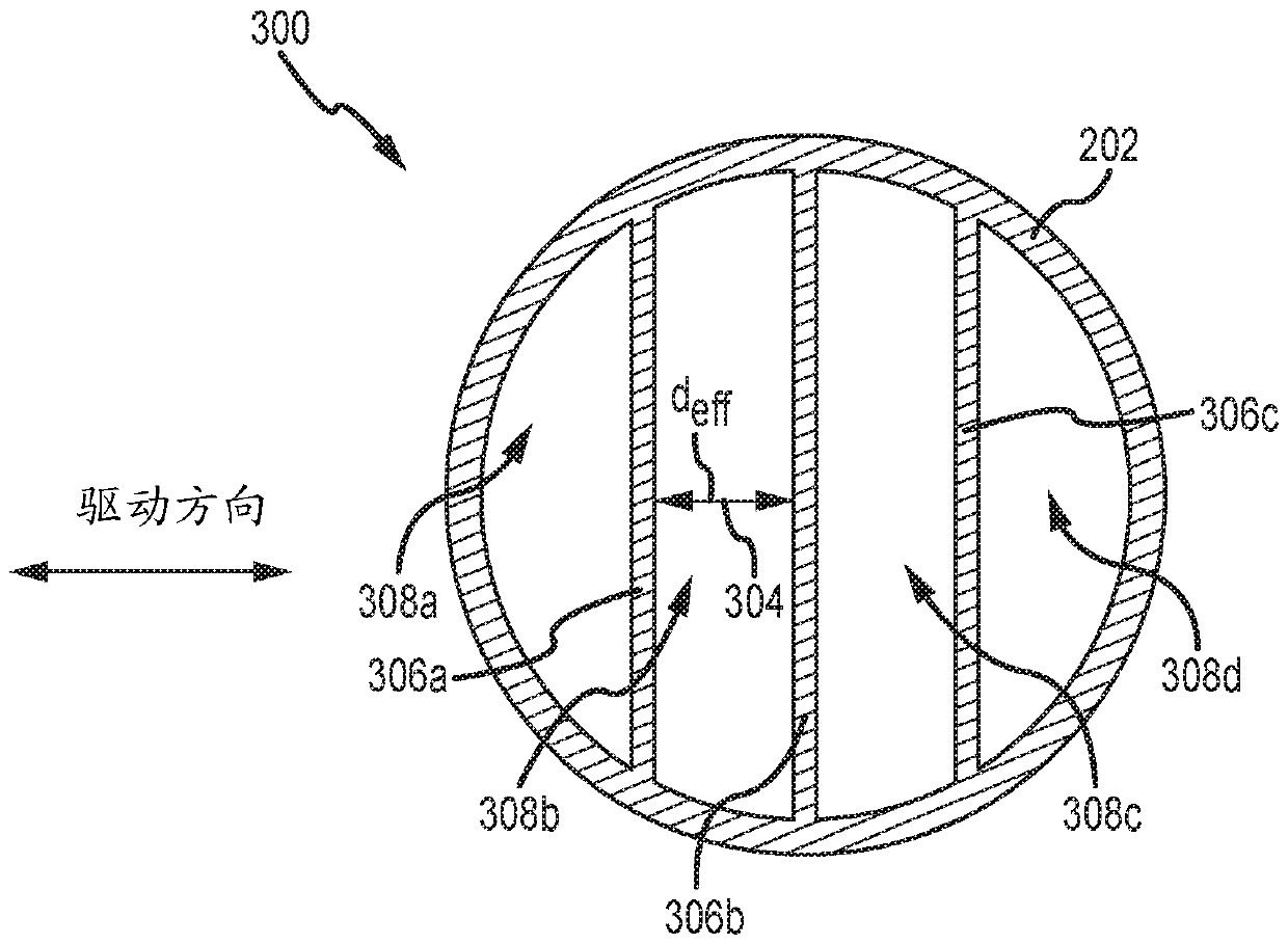
[0007] However, when channel dividers are incorporated into existing vibrating meter designs, such as in multi-channel flow tubes with circular diameters, the channels reduce the cross-sectional area available for flow through the flow tubes.

Method used


Image

  • Vibratory meter with pointed flow tube
  • Vibratory meter with pointed flow tube
  • Vibratory meter with pointed flow tube

Examples


Embodiment Construction

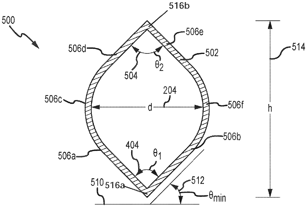
[0056] The present disclosure describes a vibrating meter including a flow tube having a pointed section and a method of forming a vibrating meter including a flow tube having a pointed section.

[0057] figure 1 A vibrating meter 5 with a multi-channel flow tube 130 according to an example is depicted. Such as figure 1 As shown in the figure, the vibrating meter 5 includes a meter assembly 10 and meter electronics 20. The meter assembly 10 is responsive to the mass flow rate and density of the process material. The meter electronics 20 is connected to the meter assembly 10 via leads 100 to provide density, mass flow rate and temperature information and other information through the communication path 26. Information and commands may also be received at the meter electronics 20 via the communication path 26.

[0058] The Coriolis flowmeter structure is described, but this is not intended to be limiting. The skilled person will easily understand that this application can be pra...


PUM


Abstract

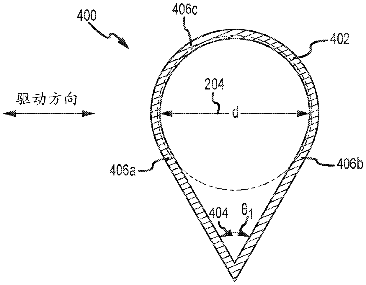
A first and second vibratory meter (5), and methods of manufacturing the same are provided. The first vibratory meter includes a pickoff (170l), a driver (180), and a flow tube (400) comprising a tubeperimeter wall with: a first substantially planar section (406a), a second substantially planar section (406b) coupled to the first substantially planar section to form a first angle theta1 (404), and a first curved section (406c). The second vibratory meter includes a pickoff, a driver, and a flow tube (700) comprising a tube perimeter wall with: a first substantially planar section (706a), a second substantially planar section (706b) coupled to the first substantially planar section to form a first angle theta1(704), a third substantially planar section (706c), a fourth substantially planarsection (706d), and a fifth substantially planar section (706e).

Description

Technical field [0001] The examples described below relate to vibrating meters and flow tubes for vibrating meters. More specifically, the example relates to a vibrating meter including a flow tube with a pointed section. Background technique [0002] Vibration meters (such as Coriolis mass flow meters and vibrating densitometers) generally operate by detecting the movement of a vibrating flow tube containing flowing material. The properties associated with the material in the flow tube (such as mass flow, density, etc.) can be determined by processing measurement signals received from the motion transducer associated with the flow tube. Vibration meters have meter assemblies that have one or more flow tubes in a straight configuration or a curved configuration. Each flow tube configuration in a Coriolis mass flowmeter has a set of natural vibration modes, which can be a simple bending type, torsion type or coupling type. Each flow tube can be driven to oscillate in a preferre...

Claims


Application Information

Patent Timeline
Patent Type & Authority Applications(China)
IPC IPC(8): G01F1/84G01F15/00
CPCG01F1/8404G01F1/8409G01F1/8468G01F1/8477G01F1/8486G01F1/8495G01F15/00G01F1/8422G01F1/8427
Inventor M.J.贝尔J.魏因施泰因M.N.德赛C.R.格里芬
Owner MICRO MOTION INC
Learn More