
Gyro

A gyro and gyro-tip technology, applied in the directions of gyro, entertainment, toys, etc., can solve the problems of single running track of gyro-tip and poor impact stability, and achieve the effect of enhancing fun and entertainment.

Pending Publication Date: 2020-04-03
GUANGZHOU SUNBOY ANIMATION & TOYS CO LTD
View PDF0 Cites 0 Cited by
  • Summary
  • Abstract
  • Description
  • Claims
  • Application Information

AI Technical Summary

Problems solved by technology

[0004] The purpose of the present invention is to provide a gyroscope to solve the technical problems in the prior art that the gyroscope has a single gyroscope running track and poor impact stability.

Method used


Image

  • Gyro
  • Gyro
  • Gyro

Examples


Embodiment 1

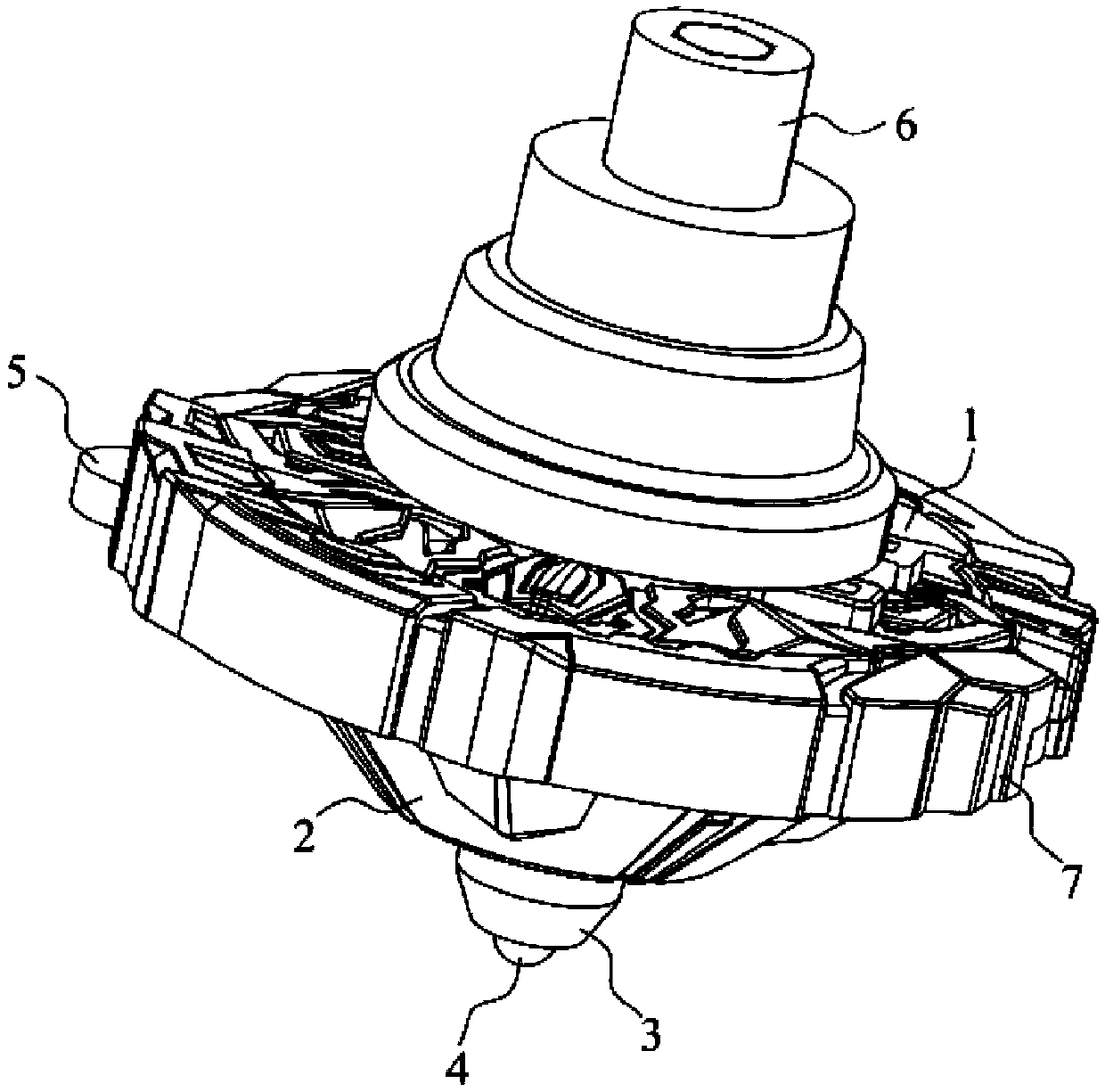
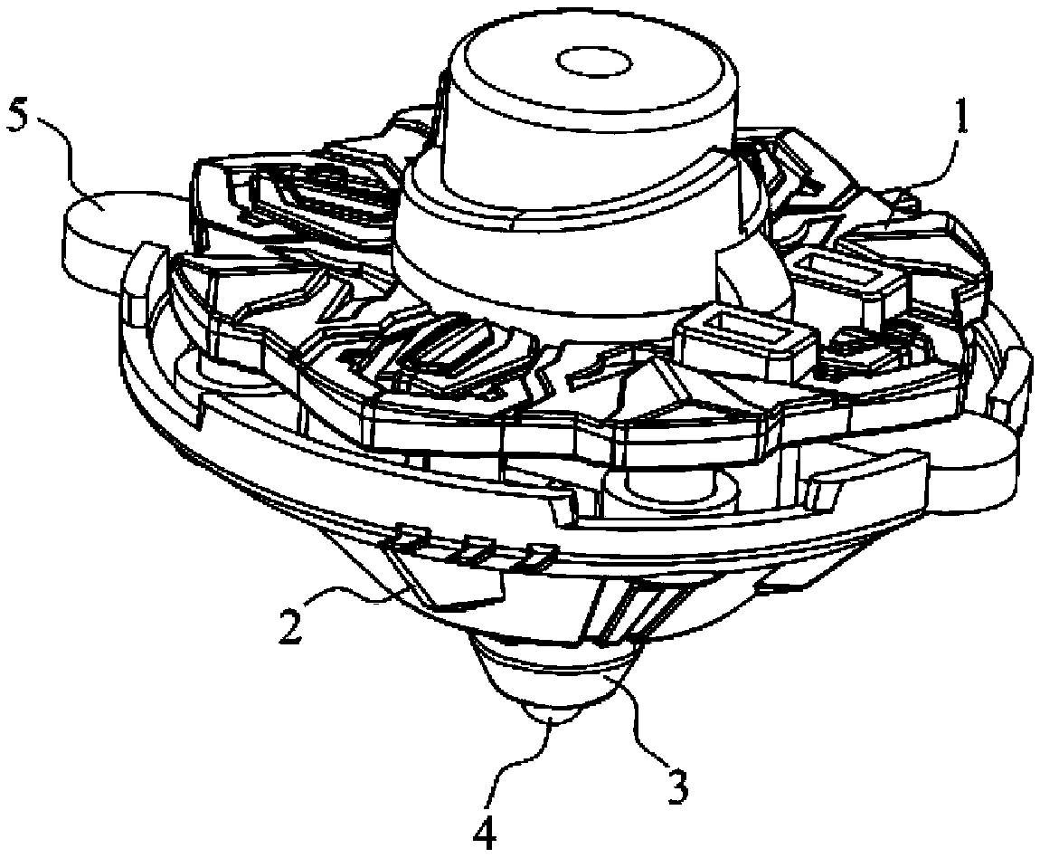
[0050] see Figure 1 to Figure 15 , the embodiment of the present invention provides a gyroscope, which includes a fixed cover 1 and a bottom cover 2, the center of the cover 1 and the bottom cover 2 is provided with a central shaft 4 that can slide along the first direction, and the center of the bottom cover 2 A shaft hole is provided at the central shaft 4, and the central shaft 4 is penetrated in the shaft hole and can slide along the shaft hole. The first direction is the extension direction of the shaft hole. The lower end of the central shaft 4 is the first top tip 41; 2 is provided with a rod 5, the rod 5 can slide along the second direction under the action of an external force and is slidably matched with the central shaft 4, the rod 5 slides along the second direction and pushes the central shaft 4 to slide along the first direction, so that the second A top 41 extends or retracts from the shaft hole, and the top of the top switches between the first top 41 and the ...

Embodiment 2

[0069] Figure 16 to Figure 19 Embodiment 2 is shown, in which components identical or corresponding to those in Embodiment 1 are identified with reference numerals corresponding to Embodiment 1. For simplicity, only the differences between Embodiment 2 and Embodiment 1 are described. The difference is that the upper end surface 422 of the protrusion 42 abuts and fits with the limiting surface, and the second spring 9 is arranged between the protrusion 42 and the sleeve 3 .

[0070] A second stepped portion is provided inside the bushing 3 , one end of the second spring 9 abuts against the lower end surface 421 of the protrusion 42 , and the other end abuts against the second stepped portion.

[0071] When the first tip 41 of the central axis 4 is retracted to the sleeve 3, the upper end surface 422 of the protrusion 42 abuts against the first plane 53; when the first end 51 of the rod 5 is hit and slides along the second direction, The limit surface pushes the central axis ...


PUM


Abstract

The invention discloses a gyro, which belongs to the field of toys and comprises a middle shaft capable of sliding along a shaft hole and a rod piece in sliding fit with the middle shaft, wherein themiddle shaft is formed in a manner of switching from a freely rotating first gyro tip to a second gyro tip; the outer edge of the lower end of the shaft hole is provided with a second gyroscope tip; under the condition of no external force, the gyro rotates around the first gyro tip or the second gyro tip; when the external force impacts the first end of the rod piece, the rod piece pushes the middle shaft to slide in the first direction, the first gyro tip retracts into the shaft hole, and therefore the gyro rotates around the second gyro tip. When the external force impacts the second end ofthe rod piece, the rod piece pushes the middle shaft to slide in the direction opposite to the first direction, so that the first gyro tip extends out of the shaft hole, and the gyroscope rotates around the first gyroscope tip. During battle impact, when the rod piece is impacted, the middle shaft can be driven to slide, so that the gyro tip is switched between the first gyro tip and the second gyro tip, the motion trail of the gyro on the spherical battle disc is changed, and the battle process of the gyro is more splendid and vivid.

Description

technical field [0001] The invention relates to the field of toys, in particular to a spinning top. Background technique [0002] Spinning top, as a kind of competitive and recreational toy, is loved by children for its varied playing methods. The basic way of playing the existing toy top is to launch the top onto the plane through the top transmitter, and then the top rotates, or directly install a motor in the top, and drive the top to rotate through the motor. A further way of playing is to compete by turning and attacking each other, so as to improve the fun of playing. In the competition, the key to success or failure lies in the top speed, the stability of rotation and the angle of attack. [0003] However, the existing gyroscopes generally only have one gyro tip. During use, their running track is relatively single, and the interest is low, which cannot meet the current requirements of children in games or competitions; On the base or fixedly installed on the centr...

Claims


Application Information

Patent Timeline
IPC IPC(8): A63H1/00
CPCA63H1/00
Inventor 明玉平
Owner GUANGZHOU SUNBOY ANIMATION & TOYS CO LTD
Learn More