

Chain conveyor
A chain conveyor and sprocket technology, which is applied in the direction of conveyors, conveyor objects, transportation and packaging, etc., can solve the problems of chain wear, slow transportation, low efficiency, etc., and achieve long service life, low noise and friction, The effect of improving transportation efficiency
- Summary
- Abstract
- Description
- Claims
- Application Information
AI Technical Summary
Problems solved by technology
Method used
Image

Examples
Embodiment 1
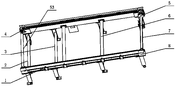
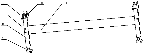
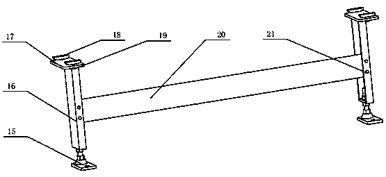
[0028] Embodiment 1: as Figure 1-11 As shown, a chain conveyor includes a support device, a transmission device, and a motor; the support device includes a combination leg 2, a sliding leg 3, a pull rod 6, a motor bracket 7, and a support rod 53, and the transmission device includes a guide rail combination 1 , the driven part 4, the driving part 5, the frame beam 8, the combined leg 2 is connected to the driven end of the frame beam 8 by bolts, the sliding leg 3 is aligned and installed in the chute at the bottom of the frame beam 8, and the motor bracket 7 Welded on the active end of the frame beam 8 and a motor is installed on it; the middle parts of the left and right frame beams 8 are connected by bolts to two pull rods 6, and the upper end of the driven end of the frame beam 8 is bolted to the support rod 53, increasing the conveyor Rigidity, in order to bear a large weight without deformation, to ensure the stability of the transportation process, the two sides of the ...
PUM
 Abstract
Description
Claims
Application Information