Multi-loop self-lubricating gear pump for numerical control machine tool

A technology of CNC machine tools and gear pumps, which is used in lubrication pumps, engine lubrication, pumps, etc., can solve the problems of insufficient lubricating oil filling, low lubrication degree of guide rails, different pressures, etc. Increase the effect of traffic

Inactive Publication Date: 2020-11-17
GUANGZHOU LIANJIANG SOFTWARE DEV LLC
View PDF0 Cites 0 Cited by
  • Summary
  • Abstract
  • Description
  • Claims
  • Application Information

AI Technical Summary

Problems solved by technology

[0003] Based on the inventor's discovery above, the existing multi-circuit self-lubricating gear pump for numerically controlled machine tools mainly has the following deficiencies. The different distances cause the lubrica

Method used


Image

  • Multi-loop self-lubricating gear pump for numerical control machine tool
  • Multi-loop self-lubricating gear pump for numerical control machine tool
  • Multi-loop self-lubricating gear pump for numerical control machine tool

Examples


Example Embodiment

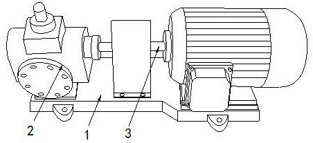
[0026] Example 1: Please refer to Figure 1-Figure 6 , The specific embodiments of the present invention are as follows:

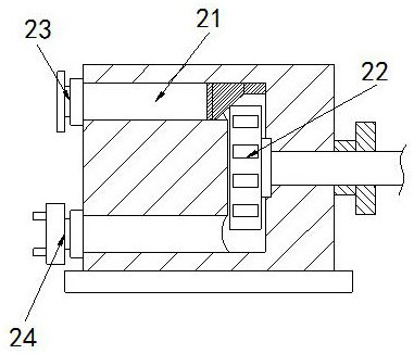
[0027] The structure includes a chassis 1, a gear pump 2, and a power shaft 3. The top of the chassis 1 is welded with a gear pump 2. The power shaft 3 is installed at the rear end of the gear pump 2, and the gear pump 2 includes a flow groove 21, The gear 22, the oil inlet 23, and the oil outlet 24. The circulation groove 21 is U-shaped and is located in the middle of the gear pump 2. The gear 22 is connected to the end of the power shaft 3 and is located in the circulation groove At the rear end of 21, the oil inlet 23 is arranged at the upper port of the circulation groove 21, and the oil outlet 24 is arranged at the lower port of the circulation groove 21.

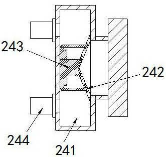
[0028] The oil outlet 24 includes an oil collecting groove 241, an oil passing plate 242, an adjusting device 243, and a diversion hole 244. The oil collecting groove 241 is arranged in the middle of th...

Example Embodiment

[0033] Example 2: Please refer to Figure 7-Figure 8 , The specific embodiments of the present invention are as follows:

[0034] The oil baffle a34 includes a gear shaft c1, a flow guide groove c2, a return block c3, and a contact block c4. The gear shaft c1 is arranged at the rear end of the oil baffle a34, and the flow guide groove c2 is provided with two, And is located at the bottom of the oil baffle a34, the return block c3 is provided with more than ten, and they are distributed across the upper end of the diversion groove c2, the contact block c4 is arranged at the front end of the oil baffle a34, the diversion groove c2 is arc-shaped, and the port at the back end is larger than the port at the front end, which is conducive to allowing the lubricating oil to circulate in one direction and speeding up the flow of lubricating oil.

[0035] The contact block c4 includes a rewind spring c41, a rubber head c42, and a bump c43. The rewind spring c41 is nested on the side end of ...


PUM


Abstract

The invention discloses a multi-loop self-lubricating gear pump for a numerical control machine tool. The gear pump structurally comprises a base plate, a gear pump body and a power shaft, the gear pump body is welded to the top of the base plate, the power shaft is installed at the rear end of the gear pump body, the gear pump body comprises a circulating groove, a gear, an oil inlet and an oil outlet, and the oil outlet comprises an oil collecting groove, an oil passing plate, an adjusting device and a flow dividing hole; the adjusting device comprises a supporting block, a backflow groove and a triggering device; and the triggering device comprises a backflow groove, a flow guide block, a flow dividing hole, an oil baffle and a reset device. The principle that the oil pressure in a guide rail is large is utilized, thus lubricating oil impacts the oil baffle, the reset device slowly drives the oil baffle to be opened, the flow of the lubricating oil is increased, the guide rail can be fully filled with the lubricating oil quickly, and the lubricating degree in the guide rail is guaranteed.

Description

Technical field [0001] The invention relates to the field of numerical control machine tools, in particular to a gear pump for multi-loop self-lubricating numerical control machine tools. Background technique [0002] In the guide rail lubrication system of large and high-precision CNC machine tools, the hydrostatic lubrication system eliminates the crawling problem of the machine tool guide through hydrostatic support, ensures the durability and safety of the machine tool guide rail, and improves the positioning accuracy of the workpiece, thereby improving the machining accuracy of the CNC machine tool For large-scale CNC machine tools, the longer the machine tool rail, the more oil supply points and the more oil to be supplied, to ensure the lubrication of the CNC machine tool during operation. [0003] Based on the above, the inventor found that the existing gear pump for multi-circuit self-lubricating CNC machine tools mainly has the following deficiencies. For example, when th...

Claims


Application Information

Patent Timeline
IPC IPC(8): F16N13/20F04C13/00F04C2/10F04C15/06F04C15/00F04C14/24
CPCF04C2/10F04C13/002F04C14/24F04C15/00F04C15/064F16N13/20
Inventor 郭建业
Owner GUANGZHOU LIANJIANG SOFTWARE DEV LLC
Why Eureka
Try Eureka