Method and device for measuring axial assembly clearance of motor bearings
A technology of motor bearing and measurement method, which is applied in the direction of measurement device, mechanical bearing test, and optical device, etc., can solve the problems of low accuracy, low efficiency, and easy bearing damage of manual measurement.
- Summary
- Abstract
- Description
- Claims
- Application Information
AI Technical Summary
Problems solved by technology
Method used
Image
Examples
Embodiment 1
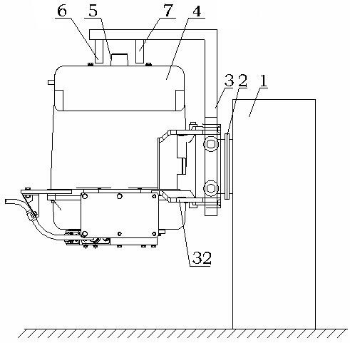
[0036] Such as figure 1 As shown, the tested motor bearing assembly axial clearance measuring device includes the tested motor displacement device and the laser measurement device, wherein the tested motor displacement device includes the main base 1, the flange plate 2, the displacement plate 3 and the Fastening frame 32. The main base 1 is provided with a servo motor, the servo motor is connected to the flange 2, and the displacement plate 3 is connected to the flange 2, and then the support 31 and the fastening frame 32 are fixedly connected to the displacement plate 3 superior. The fastening frame 32 is also fixedly connected with the motor casing 4 under test. In order to prevent the motor under test from loosening between the fastening frame 32 and the motor casing 4 under test, the fastening frame 32 will be in contact with the motor casing 4 under test. Multiple parts are fixedly connected.
[0037] The laser measurement device includes a laser transmitter 7 and a l...
Embodiment 2
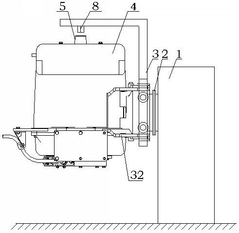
[0040] Such as figure 2 As shown, the difference between this embodiment and Embodiment 1 is that the laser measuring device in this embodiment is a reflective laser sensor 8, and the reflective laser sensor 8 is provided with a laser emitting device and a laser receiving device, and the laser emitting device It is distributed side by side with the laser receiving device in the reflective laser sensor 8 . The motor under test is placed vertically, and when the axial direction of the motor under test is consistent with the vertical direction, the reflective laser sensor 8 is directly above or directly below the rotating shaft 5, and the laser emitting device and the laser receiving device are placed on the rotating shaft 5 respectively. both sides of the central axis. In order to distinguish the laser transmitter 7 and the laser receiver 6 in the first embodiment, the laser transmitter 7 and the laser receiver 6 in the reflective laser sensor 8 in this embodiment are replaced...
PUM
 Abstract
Description
Claims
Application Information
 - R&D
- Intellectual Property
- Life Sciences
- Materials
- Tech Scout
- Unparalleled Data Quality
- Higher Quality Content
- 60% Fewer Hallucinations
Browse by: Latest US Patents, China's latest patents, Technical Efficacy Thesaurus, Application Domain, Technology Topic, Popular Technical Reports.
© 2025 PatSnap. All rights reserved.Legal|Privacy policy|Modern Slavery Act Transparency Statement|Sitemap|About US| Contact US: help@patsnap.com


