Wire smoothing device for cable installation

A cable installation and wire seat technology, which is applied in cable installation devices, cable installation, equipment for connecting/terminating cables, etc. problems, to achieve the effect of speeding up the line drawing speed and adapting to a wide range

Active Publication Date: 2020-04-17
烟台天源送变电工程有限公司
View PDF14 Cites 3 Cited by
  • Summary
  • Abstract
  • Description
  • Claims
  • Application Information

AI Technical Summary

Problems solved by technology

[0004] Aiming at the deficiencies of the prior art, the present invention provides a line-strapping device for cable installation, which solves the time-consuming and labor-intensive use of this traditional manual method, which greatly increases the construction period of power plants and substations, and affects the progress of subsequent acceptance and commissioning. The problem

Method used


Image

  • Wire smoothing device for cable installation
  • Wire smoothing device for cable installation
  • Wire smoothing device for cable installation

Examples


Embodiment 2

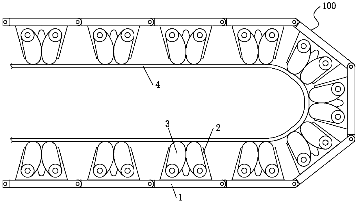
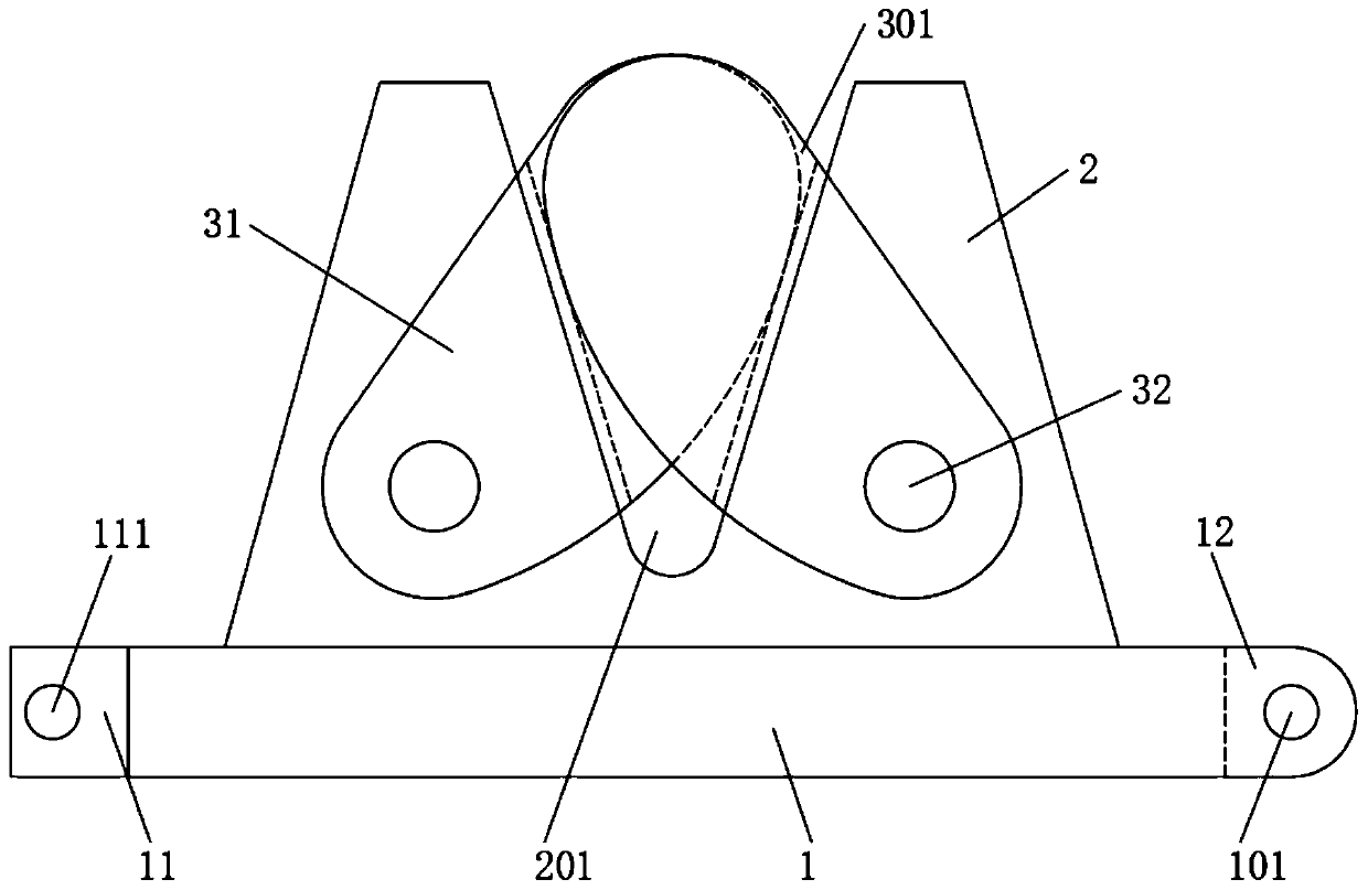
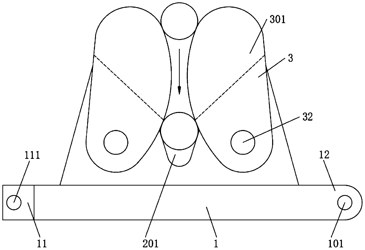
[0028] The difference from Embodiment 1 is that the threading seat 2 is evenly installed on both sides of the chain link plate 1, and multiple cables can be placed in the slots 201 of different threading seats 2 at the same time, and more cables can be accommodated. Compared with Example 1, the installation amount of cables is doubled, and the speed of threading is greatly accelerated, and then the threading device 100 is pulled to complete the threading work of multi-strand cables. The chain link plates 1 are hinged and rotated with each other, so that the thread smoothing device 100 can not only be in a plane shape, but also can be bent into an arc or a circle, and can be selected according to the requirements of thread smoothing, making the thread smoothing device 100 more flexible. After finishing the line, you can also paste the self-adhesive tape 4 on the outside of the cable extruding mechanism 3 to fix the cable, serve as a wire clip, and position the cable, and it is r...

Embodiment 3

[0030] The difference from Embodiment 1 is that the wire-stripping seats 2 are installed alternately on both sides of the chain link plate 1, and multiple cables can be placed in the wire grooves 201 of different thread-strapping seats 2 at the same time. According to the distribution situation, any combination of the threading seat 2 is used to adapt to the state of threading in more complicated situations, so that the threading speed is faster, and then the threading device 100 is pulled to complete the threading work of the multi-strand cables. The chain link plates 1 are hinged and rotated with each other, so that the thread smoothing device 100 can not only be in a plane shape, but also can be bent into an arc or a circle, and can be selected according to the requirements of thread smoothing, making the thread smoothing device 100 more flexible. After finishing the line, you can also paste the self-adhesive tape 4 on the outside of the cable extruding mechanism 3 to fix th...


PUM


Abstract

The invention relates to a wire smoothing device for cable installation. The device comprises a wire smoothing device, wherein the wire smoothing device comprises a plurality of chain link units hinged with each other, each chain link unit comprises a chain link plate, a wire smoothing seat, a cable extrusion mechanism and a self-adhesive tape, one end of the chain link plate is fixedly provided with a hinged part smaller than the width of the chain link plate, and the other end of the chain link plate is provided with a hinged protective plate complementary to the hinged part; by arranging the wire smoothing device composed of a plurality of chain link units hinged with each other, wherein each chain link units comprises a chain link plate, a wire smoothing seat, a cable extrusion mechanism and a self-adhesive tape, the wire smoothing seat is provided with a 60-degree V-shaped wire duct, the V-shaped wire duct can accommodate cables and cables with different diameters, the two sides of the wire smoothing seat are provided with the cable extrusion mechanisms, each cable extrusion mechanism comprises two groups of extrusion plates arranged at the two sides of the wire smoothing seat, and the two extrusion plates at the same side are mutually extruded inwards to limit the cables in the wire duct.

Description

technical field [0001] The invention relates to the technical field of cable installation accessories, in particular to a threading device for cable installation. Background technique [0002] The cable is usually a rope-like cable twisted by several or groups of wires [at least two in each group]. Each group of wires is insulated from each other and is often twisted around a center. Insulated covering layer, an insulated wire composed of one or more mutually insulated conductive cores placed in a sealed sheath, and a protective covering layer can be added outside it, used to transmit, distribute electric energy or transmit electrical signals, it is different from ordinary The difference between the wires is mainly that the cable size is larger and the structure is more complicated. The construction process of power plants and substations involves the process of controlling cable laying, wiring, and checking wires. Among them, the wiring work accounts for more than 70% of th...

Claims


Application Information

Patent Timeline
Patent Type & Authority Applications(China)
IPC IPC(8): B21F1/02H02G1/14H02G1/00
CPCB21F1/02H02G1/00H02G1/14
Inventor 章杰
Owner 烟台天源送变电工程有限公司
Why Eureka
Try Eureka