A threading device for cable installation

A technology of cable installation and wire holder, which is applied in the direction of cable installation device, cable installation, equipment for connecting/terminating cables, etc., which can solve the problems of time-consuming and labor-intensive, increasing construction period of power plants and substations, affecting acceptance and commissioning progress, etc. problem, to achieve the effect of speeding up the threading speed and adapting to a wide range

Active Publication Date: 2021-08-24
烟台天源送变电工程有限公司
View PDF10 Cites 0 Cited by
  • Summary
  • Abstract
  • Description
  • Claims
  • Application Information

AI Technical Summary

Problems solved by technology

[0004] Aiming at the deficiencies of the prior art, the present invention provides a line-strapping device for cable installation, which solves the time-consuming and labor-intensive use of this traditional manual method, which greatly increases the construction period of power plants and substations, and affects the progress of subsequent acceptance and commissioning. The problem

Method used


Image

  • A threading device for cable installation
  • A threading device for cable installation
  • A threading device for cable installation

Examples


Embodiment 2

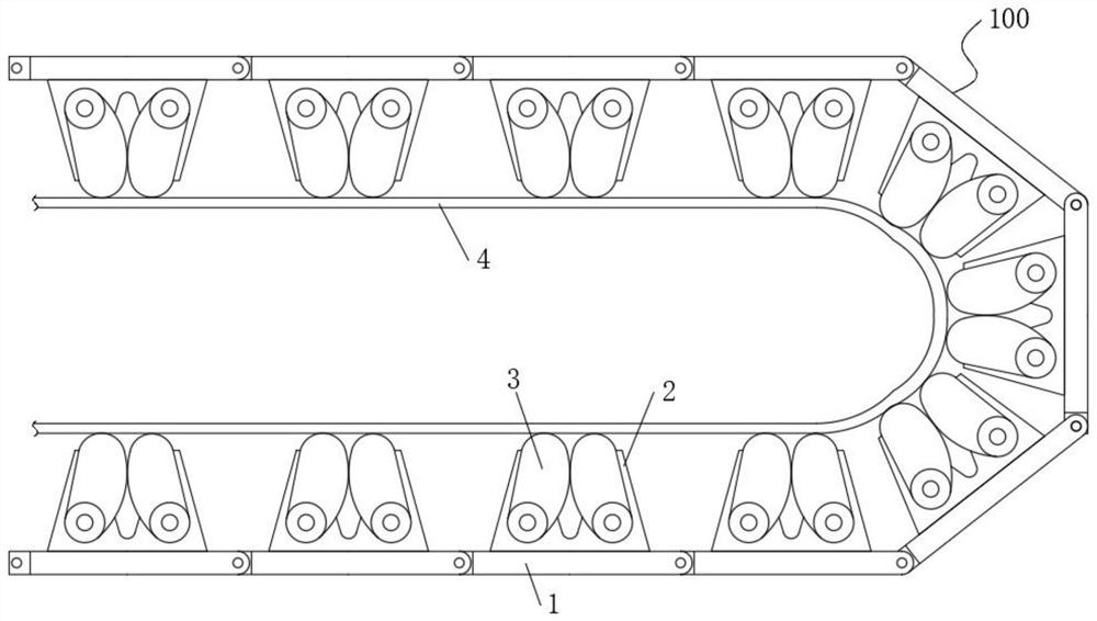
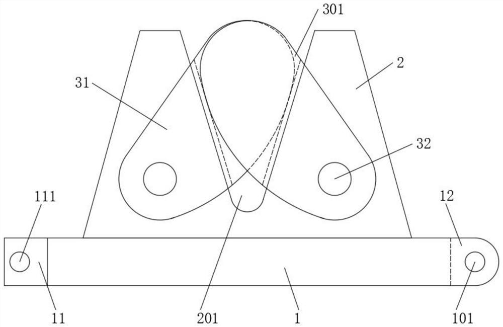
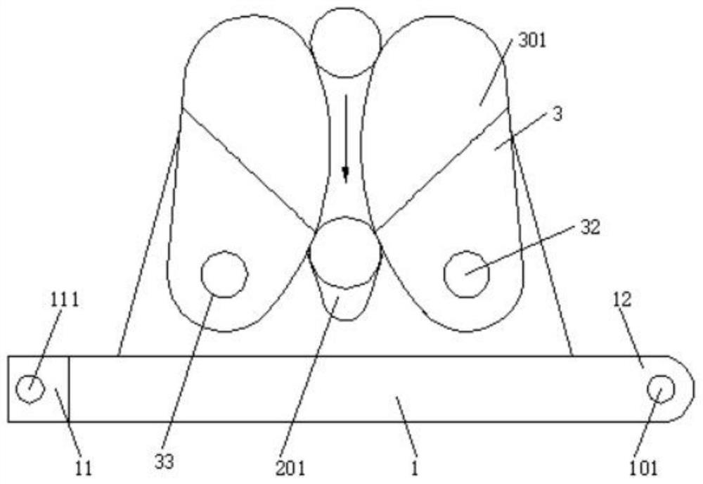
[0028] The difference from Embodiment 1 is that the wire-pulling seat 2 is evenly installed on both sides of the chain link plate 1, and multiple cables can be placed in the wire grooves 201 of different wire-pulling seats 2 at the same time, which can accommodate more cables. Compared with the first embodiment, the cable has twice the installation amount of the cable, and the speed of the cable is faster, and then the cable-stripping device 100 is pulled. The chain link plates 1 are hinged and rotated with each other, so that the thread-stripping device 100 can not only be in a plane shape, but also can be bent into an arc or circle, which can be selected according to the requirements of the thread-stripping device, so that the thread-stripping device 100 is more flexible. After the wire is stretched, the sticker 4 can also be pasted on the outside of the cable extrusion mechanism 3 to fix the cable, act as a wire clip, position the cable, and can be reused. When in use, you c...

Embodiment 3

[0030] The difference from Embodiment 1 is that the wire-pulling bases 2 are installed on both sides of the chain link plate 1 in a staggered manner, and multiple cables can be placed in the wire grooves 201 of different wire-pulling bases 2 at the same time. According to the distribution situation, any combination of the wire-pulling seat 2 can be used to adapt to the wire-pulling state of more complicated situations, so that the wire-pulling speed is faster, and then the wire-pulling device 100 is pulled to complete the wire-pulling work on the multi-strand cables. The chain link plates 1 are hinged and rotated with each other, so that the thread-stripping device 100 can not only be in a plane shape, but also can be bent into an arc or circle, which can be selected according to the requirements of the thread-stripping device, so that the thread-stripping device 100 is more flexible. After the wire is stretched, the sticker 4 can also be pasted on the outside of the cable extr...


PUM


Abstract

A wire-stripping device for cable installation, comprising a wire-stripping device, which includes several mutually hinged chain link units, and the chain link units include a chain-link plate, a wire-stripping seat, a cable extrusion mechanism and a Dry adhesive tape, one end of the link plate is fixed with a hinge part smaller than the width of the link plate, and the other end of the link plate is provided with a hinge guard plate complementary to the hinge part; by setting several A thread winder composed of mutually hinged chain link units, in which the chain link unit includes a chain link plate, a thread thread seat, a cable extrusion mechanism and a self-adhesive tape, and a "V" with an angle of 60 degrees The "V" shaped wire groove can accommodate cables and cables of different diameters. The two sides of the threading seat are equipped with a cable extrusion mechanism. The cable extrusion mechanism includes two sides of the threading seat Two sets of extrusion plates on one side, and two extrusion plates on the same side press each other inward to limit the cable in the wire groove.

Description

technical field [0001] The invention relates to the technical field of cable installation accessories, in particular to a wire-stripping device for cable installation. Background technique [0002] The cable is usually a rope-like cable formed by twisting several or several groups of conductors [at least two in each group]. Each group of conductors is insulated from each other and often twisted around a center. Insulated cover layer, which is an insulated wire composed of one or more mutually insulated conductive cores placed in a sealed sheath, and a protective cover layer can be added to it for transmission, distribution of electrical energy or transmission of electrical signals. The main difference between the wires is that the size of the cable is larger and the structure is more complicated. The construction process of power plants and substations involves control cable laying, wiring, and wiring inspection. Among them, wiring work accounts for more than 70% of the work...

Claims


Application Information

Patent Timeline
Patent Type & Authority Patents(China)
IPC IPC(8): B21F1/02H02G1/14H02G1/00
CPCB21F1/02H02G1/00H02G1/14
Inventor 章杰
Owner 烟台天源送变电工程有限公司
Why Eureka
Try Eureka