Defrosting control method and refrigeration cabinet

A control method and technology for refrigerated cabinets, which are applied in refrigerators, refrigeration components, refrigeration and liquefaction, etc., can solve the problems of false defrosting and defrosting, evaporator frosting, economic losses of users, etc., and achieve precise control of defrosting and saving. Accurate effect of energy and defrost judgment

Active Publication Date: 2020-04-28
GREE ELECTRIC APPLIANCES INC
View PDF6 Cites 6 Cited by
  • Summary
  • Abstract
  • Description
  • Claims
  • Application Information

AI Technical Summary

Problems solved by technology

However, during the defrosting process of existing refrigerators, the temperature inside the cabinet will rise sharply to about 11°C; what is important is that in some occasions where the temperature and humidity are low, the evaporator does not have frosting, and it is still Using the time-interval natural defrosting mode will lead to ineffective defrosting; at the same time, in some places with high temperature and humidity, the evaporator frosting is very serious. At this time, still using the time-interval natural defrosting mode may cause the frost to be unable to be completely removed.
Obviously, the time-interval defrosting mode cannot be adapted to various types, so that the actual temperature in the cabinet is already higher than the temperature required by the product, resulting in shortened storage time of the product. Therefore, the defrosting mode of the existing refrigerator cannot meet the actual use needs of users. Problems such as wrong defrosting or untimely defrosting will not only waste energy but also cause economic losses to users

Method used


Image

  • Defrosting control method and refrigeration cabinet
  • Defrosting control method and refrigeration cabinet

Examples


Embodiment Construction

[0018] In order to make the technical problems, technical solutions and beneficial effects to be solved by the present invention clearer, the present invention will be further described in detail below in conjunction with the accompanying drawings and embodiments. It should be understood that the specific embodiments described here are only used to explain the present invention, not to limit the present invention.

[0019] The principle and structure of the present invention will be described in detail below in conjunction with the drawings and embodiments.

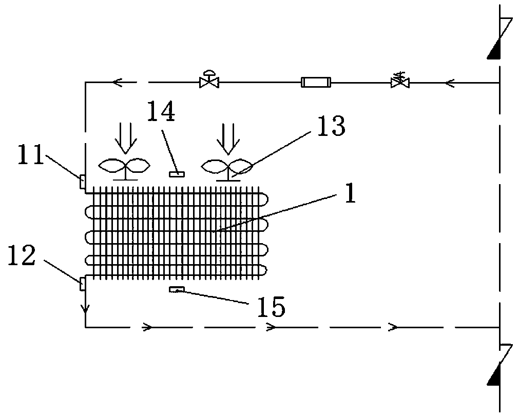
[0020] The present invention proposes a defrosting control method for a refrigerator and a refrigerator applying the method, such as figure 1 The schematic diagram of the structure of the refrigeration system in the present invention is shown, the refrigeration system includes an evaporator 1, wherein the evaporator 1 includes an inlet (refrigerant inflow end) and an outlet (refrigerant outflow end), and the inlet of the ...


PUM


Abstract

The invention discloses a defrosting control method and a refrigeration cabinet. The defrosting control method includes the steps of recording the refrigerating and cooling time when a refrigerating system is in a refrigerating and cooling mode, detecting an inlet temperature T1, an outlet temperature T2, an air inlet temperature T3 and an air outlet temperature T4 of a heat exchanger, performingdefrosting determining when T1 is smaller than 0, continuing to detect T1 when T1 is larger than 0, starting to perform defrosting when T2 is larger than 0 and the refrigerating and cooling time t islarger than or equal to a first preset time value t1 or when T2 is smaller than 0 and the refrigerating and cooling time t is larger than or equal to a second preset time value t2 or when the difference between T3 and T4 is smaller than a preset value K, and ending the defrosting when the surface temperature of the heat exchanger reaches a temperature preset value T. Compared with the prior art, defrosting determining can be more accurate by detecting whether frosting happens to an evaporator, the refrigerating system cannot perform defrosting by mistake or not in time, and the aims of precisely controlling defrosting and saving energy are realized.

Description

technical field [0001] The invention relates to the field of refrigeration equipment, in particular to a defrosting control method and a refrigerator. Background technique [0002] At present, the refrigerators on the market adopt the time-interval natural defrosting mode when defrosting, that is, defrosting is performed every once in a while. The defrosting termination condition is the termination of temperature or time. When defrosting, the unit compressor stops. For refrigeration, the fan of the air curtain cabinet continues to run, and the return air of about 14°C is used to heat the evaporator, and the temperature of the evaporator continues to rise to about 11°C, so as to achieve the effect of defrosting. However, during the defrosting process of existing refrigerators, the temperature inside the cabinet will rise sharply to about 11°C; what is important is that in some occasions where the temperature and humidity are low, the evaporator does not have frosting, and it ...

Claims


Application Information

Patent Timeline
Patent Type & Authority Applications(China)
IPC IPC(8): F25B47/02F25D11/00
CPCF25B47/022F25B2347/02F25D11/00
Inventor 孙庆一鸣莫凡龙李福良关焕豪苗志强吴明国肖勇
Owner GREE ELECTRIC APPLIANCES INC
Why Eureka
Try Eureka