Defrosting control method and air source heat pump system

A control method and air temperature technology, applied in refrigerators, refrigeration components, refrigeration and liquefaction, etc., can solve problems such as misdefrosting faults, threats to safe operation of units, energy loss, etc., to achieve accurate judgment, easy promotion and use, and low cost low effect

Inactive Publication Date: 2019-04-19
QINGDAO ECONOMIC & TECHN DEV ZONE HAIER WATER HEATER
View PDF6 Cites 16 Cited by
  • Summary
  • Abstract
  • Description
  • Claims
  • Application Information

AI Technical Summary

Problems solved by technology

[0003] In order to solve the technical problems of inaccurate judgment of defrosting conditions for existing air source heat pumps, prone to false defrosting faults, resulting in energy loss, and threatening the safe operation of the unit, the present invention proposes a defrosting control method that can solve the above problems

Method used


Image

  • Defrosting control method and air source heat pump system
  • Defrosting control method and air source heat pump system

Examples


Embodiment 1

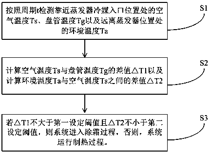
[0030] Embodiment 1, when the air source heat pump is in heating operation under the condition of low ambient temperature in winter, frost usually forms on the surface of the finned tubes of the evaporator. During the frosting process, the distribution of the frost layer on the fin surface is related to the The temperature of the surface of the tube is related to the temperature of the surface of the finned tube and the flow and heat transfer characteristics of the refrigerant. Studies have shown that when the low-temperature refrigerant flows in the tube, the pressure of the refrigerant will gradually decrease due to the frictional resistance of the tube wall. The impact of resistance pressure drop is very large, and the change of refrigerant flow rate is related to the gas-liquid ratio of refrigerant. The larger the proportion of liquid (the greater the mass), the smaller the refrigerant flow rate (usually between 0.5-1.0m / s) , with the heat absorption and vaporization of th...

Embodiment 2

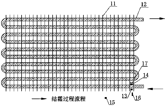
[0052] Embodiment 2. This embodiment proposes an air source heat pump system, including a compressor and an evaporator. The evaporator includes a coil tube 11 and a coil tube 12 fixed on the fin 11. On one side of the fin 11 and the coil tube, There is also a fan (not shown in the figure) on the side. The fins 11 and the coil 12 are perpendicular to each other to form a fin tube. The fan is located on one side of the fin 11 and the coil 12. When the fan is running, the suction air flows through the fins. The pipe structure exchanges heat with the low-temperature refrigerant in the coil 12. The flow direction of the refrigerant during the heating process of the heat pump system is shown by the arrow. A first temperature sensor 13 is installed near the refrigerant inlet of the evaporator. The second temperature sensor 14, the temperature sensing surface of the second temperature sensor 14 is closely attached to the coil pipe, and is used to detect the temperature of the coil pipe...


PUM


Abstract

The invention discloses a defrosting control method and an air source heat pump system. The method comprises the following steps that (1), the air temperature Ts and the coil pipe temperature Tg at the position close to a refrigerant inlet of an evaporator, and the ambient temperature Ta away from the evaporator are detected according to the period t; (2), the difference value delta T1 between theair temperature Ts and the coil pipe temperature Tg is calculated, and the difference value delta T2 between the ambient temperature Ta and the air temperature Ts is calculated; and (3) if the deltaT1 is not larger than the first set threshold value and the delta T2 is not smaller than the second set threshold value, the system enters the defrosting process, and otherwise, the system operates the heating process. According to the defrosting control method, the defrosting judgment mechanism is based on growth characteristics and distribution rules of a frost layer in the frosting process of the evaporator, so that judgment is accurate, the phenomenon that an existing double-temperature-sensor method frequently conducts false defrosting in a cold drying environment is avoided, so that theenergy efficiency ratio and the running reliability of the system are greatly improved.

Description

technical field [0001] The invention relates to the technical field of defrosting control, in particular to a defrosting control method and a heat pump water heater. Background technique [0002] When the air source heat pump is running in winter, the outdoor heat exchanger usually frosts. When the frost layer reaches a certain thickness, the heat exchanger needs to be defrosted. At present, the most widely used defrosting method is indoor / outdoor Dual temperature-time method, this method is simple, cheap, and easy to implement, but it is often used in cold and dry conditions (such as North China), but accidental defrosting accidents often occur. Research shows that under this condition, "no frost" "Defrosting" accidents accounted for as high as 70% of the total number of defrosting times, resulting in a significant loss of the effective heat supply of the system, a sharp drop in COP, and a threat to the safe operation of the unit, greatly reducing the reliability of the sys...

Claims


Application Information

Patent Timeline
Patent Type & Authority Applications(China)
IPC IPC(8): F25B47/00F25B49/02
CPCF25B47/00F25B49/02F25B2600/01F25B2700/02
Inventor 赵洪运高本法庄长宇蒋建平彭海燕
Owner QINGDAO ECONOMIC & TECHN DEV ZONE HAIER WATER HEATER
Why Eureka
Try Eureka