Defrosting control method and air source heat pump system
A control method and technology for air temperature, applied in refrigerators, refrigeration components, refrigeration and liquefaction, etc., can solve problems such as false defrosting failure, threatening the safe operation of the unit, energy loss, etc., and achieve accurate judgment, simple structure and low cost. Effect
- Summary
- Abstract
- Description
- Claims
- Application Information
AI Technical Summary
Problems solved by technology
Method used
Image
Examples
Embodiment 1
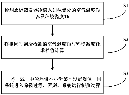
[0024] Embodiment 1. When the air source heat pump is in heating operation under the condition of low ambient temperature in winter, frost usually forms on the surface of the finned tubes of the evaporator. During the frosting process, the distribution of the frost layer on the surface of the finned tubes and the The temperature of the finned tube is related to the temperature of the surface of the finned tube and the flow and heat transfer characteristics of the low-temperature refrigerant in the tube. Studies have shown that when the cold and low temperature refrigerant flows in the tube, the pressure of the refrigerant will gradually decrease due to the frictional resistance of the tube wall. The influence of frictional pressure drop is very large, and the change of refrigerant flow rate is related to the gas-liquid ratio of refrigerant. The larger the proportion of liquid (the greater the mass), the smaller the refrigerant flow rate (usually between 0.5-1.0m / s ), with the ...
Embodiment 2
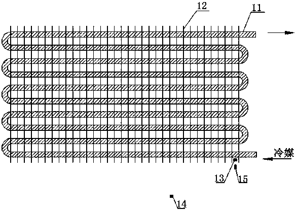
[0048] Embodiment 2, this embodiment proposes a heat pump system, which can be used as an air conditioning system, and can also be used in a heat pump water heater. The heat pump system of this embodiment includes a compressor and an evaporator, such as figure 2 As shown, the evaporator includes fins 12 and coiled tubes 11 fixed on the fins 12, and a fan (not shown in the figure) is also arranged on one side of the fins 12 and the coiled tubes 11, and the fins 12 and the coiled tubes 11 are perpendicular to each other to form finned tubes. The fan is located on one side of the fins 12 and the coiled tube 11. When the fan is running, the air sucked flows through the finned tube structure, exchanging heat with the low-temperature refrigerant in the coiled tube 11, and evaporates when the system is heating. The flow direction of the refrigerant in the evaporator is shown by the arrow in the figure. The first temperature sensor 13 is set at the position close to the refrigerant in...
PUM
 Abstract
Description
Claims
Application Information
 - R&D
- Intellectual Property
- Life Sciences
- Materials
- Tech Scout
- Unparalleled Data Quality
- Higher Quality Content
- 60% Fewer Hallucinations
Browse by: Latest US Patents, China's latest patents, Technical Efficacy Thesaurus, Application Domain, Technology Topic, Popular Technical Reports.
© 2025 PatSnap. All rights reserved.Legal|Privacy policy|Modern Slavery Act Transparency Statement|Sitemap|About US| Contact US: help@patsnap.com


