Fail judging method and analyzer

a technology of failure judging and analyzer, applied in the field of failure judging method and analyzer, can solve problems such as improper sensors

Inactive Publication Date: 2005-03-31
PHC CORP +1
View PDF3 Cites 57 Cited by
  • Summary
  • Abstract
  • Description
  • Claims
  • Application Information

AI Technical Summary

Benefits of technology

[0011] With such an analyzer, it is possible to properly implement the fail judging method provided

Problems solved by technology

Otherwise, it is determined

Method used


Image

  • Fail judging method and analyzer
  • Fail judging method and analyzer
  • Fail judging method and analyzer

Examples


Embodiment Construction

[0026] Preferred embodiments of the present invention will be described below with reference to the accompanying drawings.

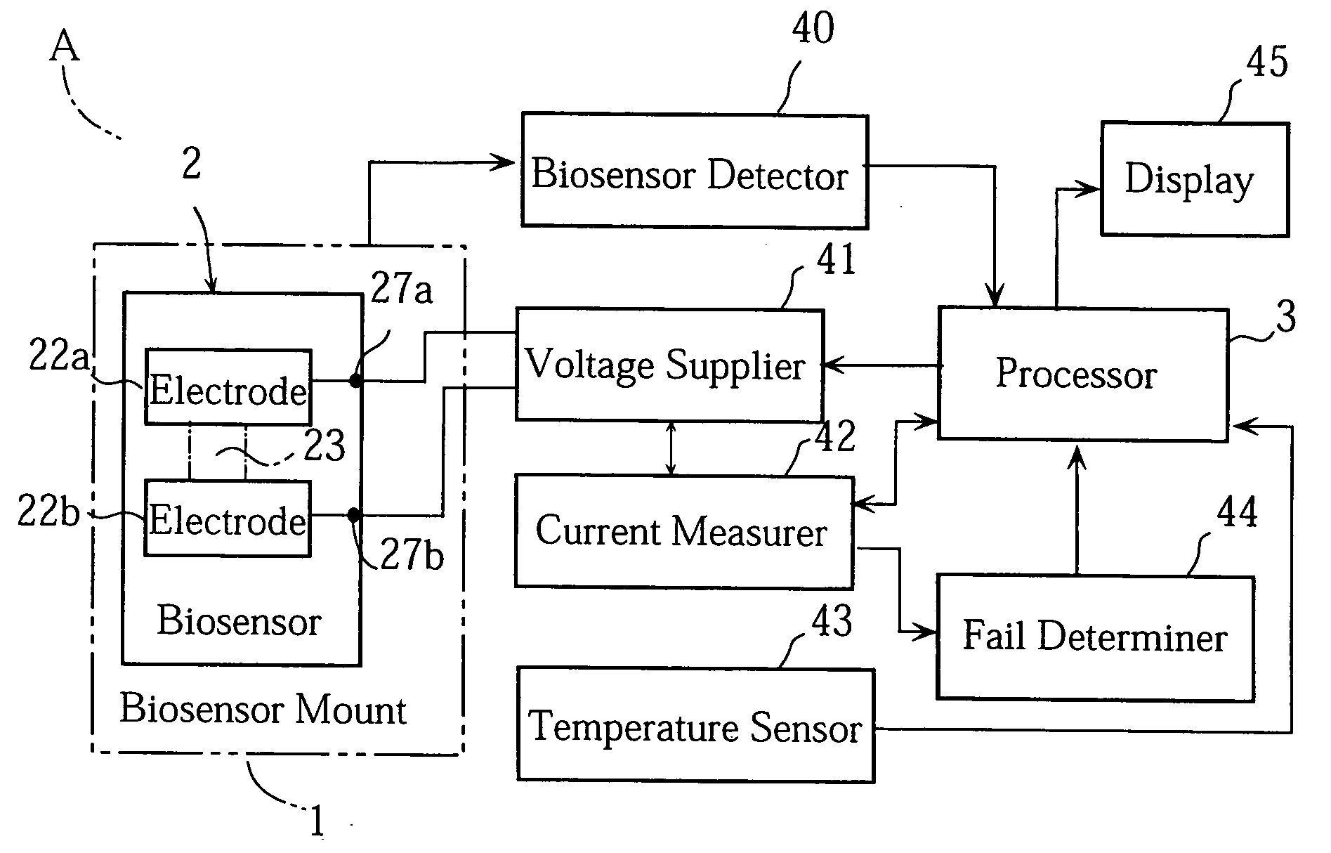
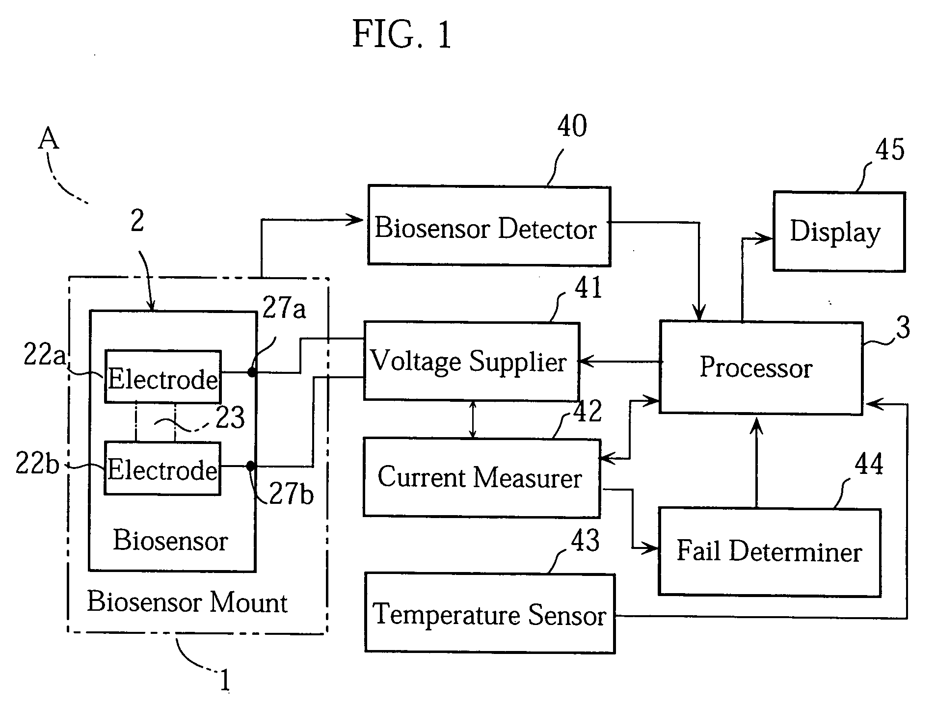
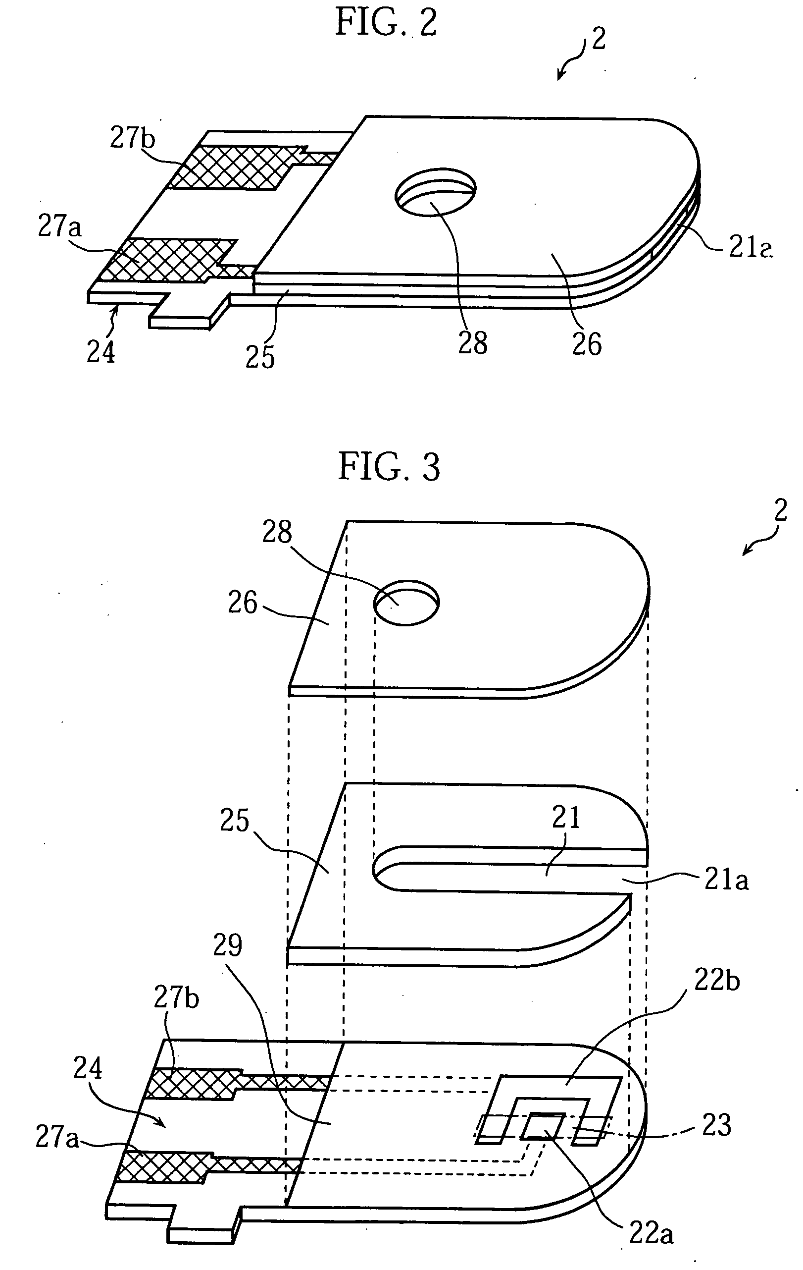
[0027]FIG. 1 shows an example of analyzer according to the present invention. The analyzer A of the illustrated embodiment utilizes a biosensor 2 shown in FIGS. 2 and 3.

[0028] As shown in FIGS. 2 and 3, the biosensor 2 includes a substrate 24 having an upper surface on which a pair of electrodes 22a and 22b, and a reagent layer 23 are provided.

[0029] The reagent layer 23 bridges between the paired electrodes 22a and 22b. The reagent layer 23 contains glucose oxidase (hereinafter abbreviated as “GOD”) and potassium ferricyanide as components to react with glucose in blood, for example. Potassium ferricyanide is an example of electron acceptor. The meaning of the electron acceptor is described above. Portions around the reagent layer 23 and the electrodes 22a, 22b are covered with an insulating film 29. Aside of the insulating film 29 is provided terminals 27a a...


PUM

PropertyMeasurementUnit
Currentaaaaaaaaaa
Electric potential / voltageaaaaaaaaaa

Abstract

An analyzer (A) includes a current measurer (42) for measuring the current flowing between paired electrodes (22a), (22b) when a sample is introduced to the reagent layer (23) of a sensor (2) and voltage is applied across the electrodes, while also including a processor (3) for analyzing the sample based on the current after a predetermined reference time point. The analyzer (A) further includes a fail determiner (44) which monitors the change of the current before and after the reference time point and determines that the sensor (2) is improper when the current change does not correspond to a predetermined current change.

Description

TECHNICAL FIELD [0001] The present invention relates to a fail judging method for checking the properness or improperness of a sensor used for analysis such as measurement of the glucose level or cholesterol level of a blood sample. It also relates to an analyzer for implementing such a fail judging method. BACKGROUND ART [0002] JP-B-2800981 discloses a technique for measuring the concentration of a particular component in a sample such as blood. The prior art is an electrochemical method utilizing a biosensor incorporating a reagent layer and a pair of electrodes. According to the method, a sample is introduced to the reagent layer of the biosensor, with a voltage applied across the paired electrodes, and then the current between the electrodes is measured. Immediately after the sample is introduced to the reagent layer, the current increases as the electrodes and the reagent layer become wet. Thus, the introduction of the sample to the regent layer can be detected based on the fac...

Claims


Application Information

Patent Timeline
IPC IPC(8): G01N27/416G01N27/49G01N33/487
CPCG01N27/3274
Inventor MORITA, YOSHIMITSUOURA, YOSHIMISHINNO, TEPPEI
Owner PHC CORP
Why Eureka
Try Eureka