Device and method for determining step-out of synchronous motor

a synchronous motor and step-out detection technology, applied in the direction of motor/generator/converter stopper, electronic commutator, dynamo-electric converter control, etc., can solve the problem of inability to accurately detect step-out, inability to obtain desired torque by synchronous motor, and inability to achieve accurate measurement and measurement, etc. problem, to achieve the effect of accurate implementation and excessive load

Inactive Publication Date: 2001-07-12
TOYOTA JIDOSHA KK
View PDF0 Cites 17 Cited by
  • Summary
  • Abstract
  • Description
  • Claims
  • Application Information

AI Technical Summary

Benefits of technology

[0008] It is an object of the invention to provide art that enables the detection of whether or not step-out has occurred in a synchronous motor over a wide range of operation state with a light computational load.
[0017] Similarly, another phenomenon we discovered, which had also never been reported before, is that when a parameter including the ratio of the predicted energy and the detected energy is used, this parameter value is substantially unaffected by the torque command value, despite fluctuation by revolution speed. The second aspect is realized from this aspect, and the presence / absence of step-out is accurately determined by comparing the parameter with a predetermined threshold value in accordance with the revolution speed. According to the second aspect, there is an advantage that the torque command value can be disregarded.
[0019] Since the torque command value and the revolution speed are values always input upon controlling of the synchronous motor, the former aspect has an advantage that the predicted energy can be immediately obtained using this value. In the latter aspect, there is a need to reference a table, a function, or the like to obtain the electric power consumed in realizing operation under the torque command value and the revolution speed. However, since it is ordinary practice in motor control to reference tables in setting the electric current to be supplied to each phase of the motor according to the torque command value, if the electric power consumption were determined together with this, there is an advantage that it can be obtained with a relatively light load. Also, torque can be acted on the rotor even when the synchronous motor is stopped. Accordingly, in this case, determination of step-out becomes difficult because the mechanical power becomes 0 in the former aspect, but in the latter aspect, there is an advantage that the detection of step-out can be accurately implemented without such difficulty.
[0020] The step-out detection of the invention may be applied when controlling the motor operation while detecting the electrical angle with a hall element or the like, but it may be more effectively applied when the electrical angle is detected without a sensor. This is because error tends to occur in the detected value of the electrical angle when operation is controlled according to the detected value of the electrical angle without a sensor, thereby leading to step-out. Also, the detection method for detecting the electrical angle without a sensor which is applied when the synchronous motor is running such that the electrical angle can be consistently detected when the error is generally within a predetermined range. Therefore it becomes very difficult to restore the motor to a normal state of operation with the detected value of the electrical angle once the detection error becomes large and step-out occurs. Further, because determination of step-out can be made with a very light load with the step-out detection device of the invention, there is an advantage that an excessive load can be prevented from being applied to the control unit even with the sensorless control which has a considerable processing load during detection of the electrical angle.

Problems solved by technology

If the detection error of the electrical angle becomes larger and the direction in which voltage is applied deviates from the proper direction, desired torque cannot be obtained by the synchronous motor.
However, in art which uses counter-electromotive voltage generated during rotation of the rotor, there were cases where step-out was not able to be accurately detected when the motor was running at high speed or when it is stopped.
Also, with the art using a combination of the effective value of current running through the coil and the power factor degree, extremely complex computation of effective value and power factor degree was necessary, which placed a heavy load on the motor control unit.
In such case, because the control unit has to bear the computational load in detecting the electrical angle, the load for detecting step-out is too large to ignore.

Method used


Image

  • Device and method for determining step-out of synchronous motor
  • Device and method for determining step-out of synchronous motor
  • Device and method for determining step-out of synchronous motor

Examples


first embodiment

[0040] F: Modified example of the first embodiment;

second embodiment

[0041] G: Second embodiment; and

[0042] H: Modified example of the second embodiment.

[0043] A: Configuration of the Unit;

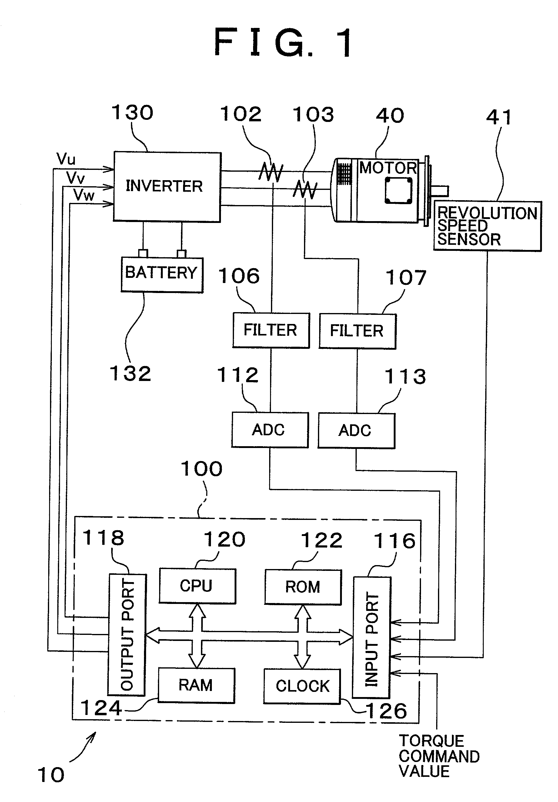
[0044] FIG. 1 is an explanatory drawing showing a schematic configuration of a motor control unit 10 as an embodiment. A step-out detection device uses hardware of the motor control unit 10 and is configured as a function of the motor control unit. Various synchronous motors are applicable to a motor 40, which is the subject of control. In this embodiment, a three-phase synchronous motor of a salient pole type with permanent magnet attached to a rotor is used. The motor control unit 10 controls the operation of the motor 40 by controlling the electric current that flows through U, V, and W phases thereof from a battery 132, a power source, by switching a transistor inverter 130. In the control of this embodiment, a sensor for detecting an electrical angle of the rotor is not provided, but instead, the electrical angle is calculated without a sensor.

[0045] The motor...


PUM


Abstract

The expected power to be output from a synchronous motor is obtained based on a torque command value and revolution speed of the motor. Meanwhile electric power consumption is detected based on voltage and current actually applied to the motor. If a parameter derived from a deviation or a ratio of the two exceeds a predetermined threshold value, it is determined that step-out has occurred. When using the deviation of the expected power from the electric power consumption as the parameter, the threshold value is determined in relation to the torque command value and the revolution speed. When using the ratio of the expected power and the electric power consumption as the parameter, the threshold value is set in relation to the revolution speed. This enables step-out to be accurately determined with an extremely light computational load.

Description

INCORPORATION BY REFERENCE[0001] The disclosure of Japanese Patent Application No. 2000-003160 filed on Jan. 12, 2000 including the specification, drawings and abstract is incorporated herein by reference in its entirety.BACKGROUND OF THE INVENTION[0002] 1. Field of the Invention[0003] The invention relates to art for detecting step-out of a synchronous motor during operation.[0004] 2. Description of Related Art[0005] In order to obtain desired torque with a synchronous motor, which is one of the AC motors, the multiphase alternating current supplied to the coil in accordance with the position of the rotor, or the electrical angle, needs to be controlled. If the detection error of the electrical angle becomes larger and the direction in which voltage is applied deviates from the proper direction, desired torque cannot be obtained by the synchronous motor. If the deviation further increases, the multi-phase alternating current becomes uncontrollable, leading to what is called a step-...

Claims


Application Information

Patent Timeline
Patent Type & Authority Applications(United States)
IPC IPC(8): H02P6/06H02P6/08H02P6/12H02P6/15H02P6/18H02P6/182
CPCH02P6/12H02P6/18H02P25/08H02P1/029
Inventor KOIDE, SATOSHIKAWABATA, YASUTOMOYAMADA, EIJI
Owner TOYOTA JIDOSHA KK
Why Eureka
Try Eureka