
Power converting controller and light-emitting diode driving circuit

a technology of power conversion controller and driving circuit, which is applied in the direction of electric variable regulation, process and machine control, instruments, etc., to achieve the effect of convenient application

Active Publication Date: 2012-05-03
GREEN SOLUTION TECH CO LTD
View PDF7 Cites 18 Cited by
  • Summary
  • Abstract
  • Description
  • Claims
  • Application Information

AI Technical Summary

Benefits of technology

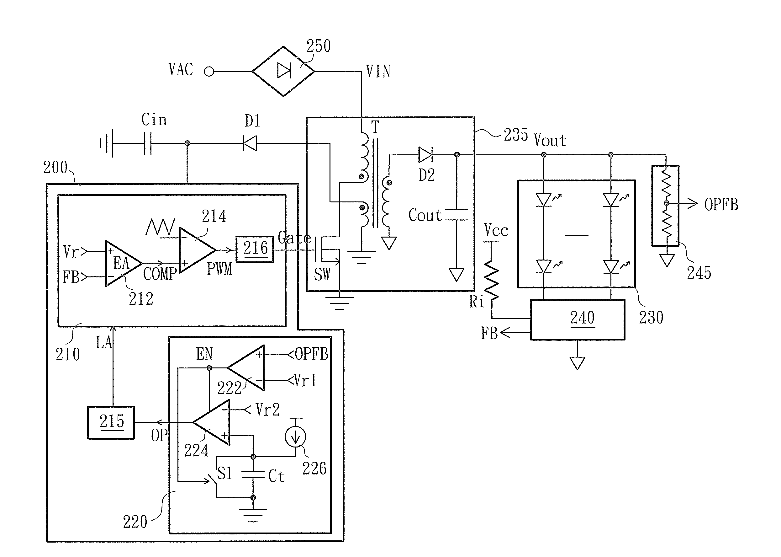
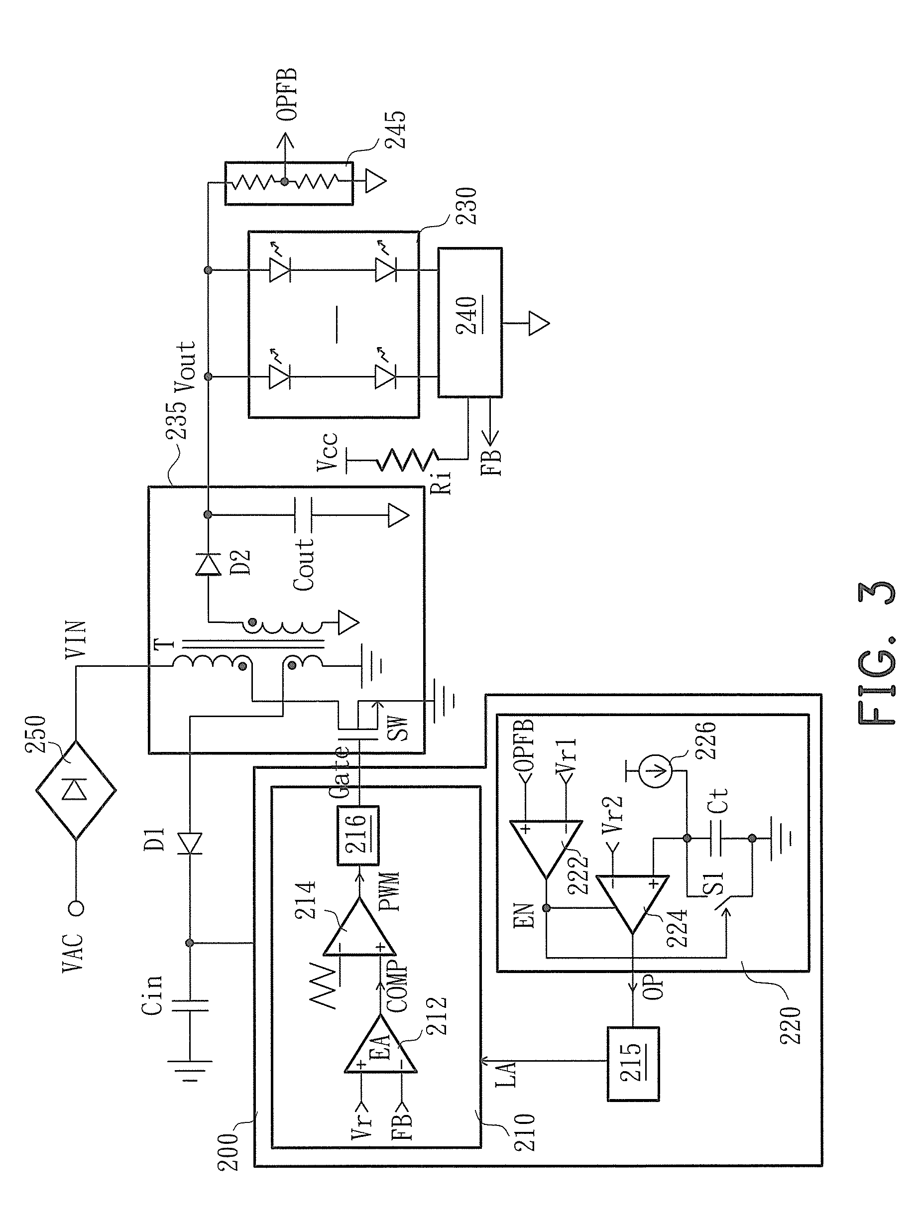
[0010]The scheme of the conventional open-circuit protection is unable to effectively distinguish an LED open-circuit from an unstable input power source, so that the prior art is unable to precisely implement the protection, in which any unstable power supply would result in fault actions of the LED driving circuit to make the LEDs stop lighting. Accordingly, the invention introduces a specific open-circuit protection unit in the LED driving controller to singly detect and judge whether the circuit needs an open-circuit protection and thus distinguishes the open-circuit protection from the under-voltage protection. Based on the idea, the invention also introduces a function of input power source sensing, so that the controller can more precisely identify and respond to the unstable situation of the input power source. In addition, the controller of the invention can also be easily applied in any circuit other than the LED driving circuit for converting power and driving different loads.

Problems solved by technology

The scheme of the conventional open-circuit protection is unable to effectively distinguish an LED open-circuit from an unstable input power source, so that the prior art is unable to precisely implement the protection, in which any unstable power supply would result in fault actions of the LED driving circuit to make the LEDs stop lighting.

Method used


Image

  • Power converting controller and light-emitting diode driving circuit
  • Power converting controller and light-emitting diode driving circuit
  • Power converting controller and light-emitting diode driving circuit

Examples


Embodiment Construction

[0019]Reference will now be made in detail to the preferred embodiments of the invention, examples of which are illustrated in the accompanying drawings. Wherever possible, the same reference numbers are used in the drawings and the description to refer to the same or like parts.

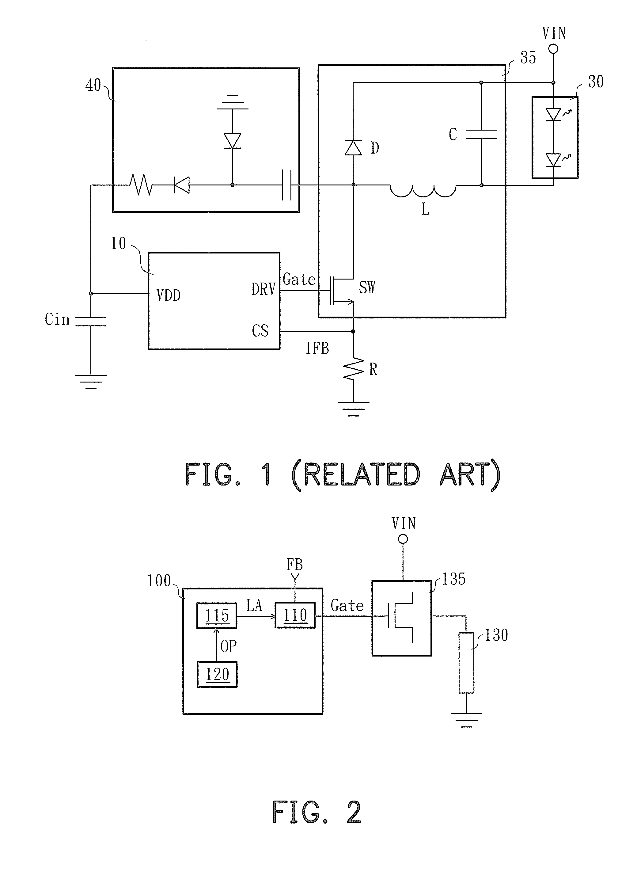
[0020]FIG. 2 is a schematic circuit diagram of a power converting circuit according to the invention. Referring to FIG. 2, a power converting circuit includes a power converting controller 100, a converting circuit 135 and a load 130. The converting circuit 135 is a switching converting circuit and includes at least a switch so as to convert an input power source VIN into an appropriate voltage source or a current source for driving the load 130 according to (at least) a control signal Gate of the power converting controller 100.

[0021]The power converting controller 100 includes a feedback control unit 110, an open-circuit judging unit 120 and a protection unit 115. The feedback control unit 110 generates th...


PUM


Abstract

A power converting controller and an LED driving circuit are provided. The power converting controller controls a converting circuit, which converts an input power source into an appropriate power source to drive a load. The power converting controller includes a feedback control unit, an open-circuit judging unit and a protection unit. The feedback control unit controls the converting circuit according to a feedback signal representing the status of the load. As the open-circuit judging unit has judged that the load is continuously in an open-circuit status for a predetermined time length, the open-circuit judging unit generates an open-circuit protection signal. The protection unit is coupled to the feedback control unit and the open-circuit judging unit so as to generate a protection signal as receiving the open-circuit protection signal and thereby the feedback control unit enters a latch status to stop controlling the converting circuit.

Description

CROSS-REFERENCE TO RELATED APPLICATION[0001]This application claims the priority benefit of China application serial no. 201010530351.5, filed Oct. 29, 2010. The entirety of the above-mentioned patent application is hereby incorporated by reference herein and made a part of this specification.BACKGROUND OF THE INVENTION[0002]1. Field of the Invention[0003]The invention generally relates to a power converting controller and a light-emitting diode driving circuit, and more particularly, to a power converting controller and a light-emitting diode driving circuit with open-circuit protection function.[0004]2. Description of Related Art[0005]In comparison with a traditional illumination light source, light-emitting diodes (LEDs) have advantages of high light-emitting efficiency, low power consumption and long lifetime, and the production cost thereof is being steadily reduced, so that people more and more broadly adopt the LEDs. An LED driving circuit usually is an isolated or a non-isol...

Claims


Application Information

Patent Timeline
IPC IPC(8): H05B37/02H02M3/335
CPCH05B33/0815H05B33/0824Y02B20/341H05B45/3725H05B45/375H05B45/385H05B45/44Y02B20/30
Inventor SHIU, SHIAN-SUNGYU, CHUNG-CHELEE, LI-MINPENG, KE
Owner GREEN SOLUTION TECH CO LTD
Learn More