A low-energy sparse CT detector, CT detection system and detection method

A detector and low-energy technology, applied in the field of CT detection, can solve the problems of inability to guarantee imaging accuracy, unfavorable equipment popularization and application, and high cost of CT detection devices, and achieve the effects of small windmill artifacts, reduced equipment costs, and guaranteed reconstruction accuracy.

Active Publication Date: 2020-12-25
BEIJING HANGXING MACHINERY MFG CO LTD
View PDF6 Cites 0 Cited by
  • Summary
  • Abstract
  • Description
  • Claims
  • Application Information

AI Technical Summary

Problems solved by technology

[0005] In view of the above analysis, the present invention aims to provide a low-energy sparse CT detector, a CT detection system and a detection method to solve the problem of high cost of CT detection devices in the prior art, which is not conducive to the popularization and application of equipment, and the reduction of cost cannot guarantee imaging Accuracy and other issues

Method used


Image

  • A low-energy sparse CT detector, CT detection system and detection method
  • A low-energy sparse CT detector, CT detection system and detection method
  • A low-energy sparse CT detector, CT detection system and detection method

Examples


Embodiment 1

[0096] A CT detector is provided with 24 rows of high-energy detectors, the distance between the centers of the two rows of high-energy detectors is 6mm; The center distance of the device is 6mm.

Embodiment 2

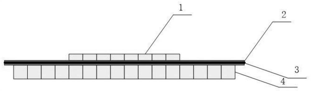
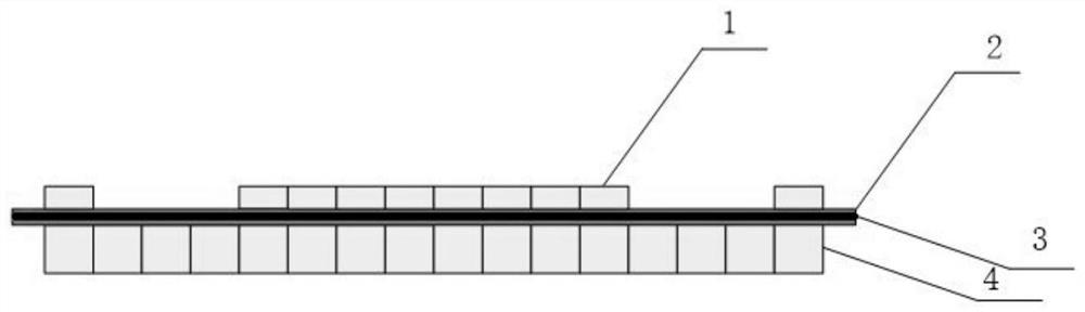
[0101] A CT detector is provided with 16 rows of high-energy detectors, and the distance between the centers of the two rows of high-energy detectors is 6 mm; it is provided with 10 rows of low-energy detectors, of which 8 rows are arranged in a centralized manner and are arranged in the middle of the high-energy detectors, and the remaining two rows A row of low-energy detectors is arranged on both sides of the detector, and the center-to-center distance between the two rows of low-energy detectors and the nearest neighbor low-energy detector is 24mm.

Embodiment 3

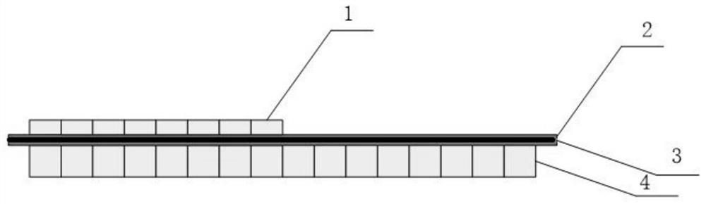
[0106] A CT detector is provided with 16 rows of high-energy detectors, and the center-to-center distance between two rows of high-energy detectors is 6mm; it is provided with 8 rows of low-energy detectors, which are arranged in a centralized manner and arranged on one side of the high-energy detectors.


PUM

PropertyMeasurementUnit
thicknessaaaaaaaaaa

Abstract

The invention discloses a low-energy sparse CT (computed tomography) detector, a CT detection system and a detection method, belongs to the technical field of CT detection, and solves the problems that a CT detection device in the prior art is high in cost, not beneficial to popularization and application of equipment, low in cost, incapable of ensuring imaging precision and the like. The CT detector comprises high-energy detectors and low-energy detectors, the high-energy detectors and the low-energy detectors are arranged in a back-to-back mode, and one high-energy detector is arranged beloweach low-energy detector; the number of rows of the high-energy detectors is larger than the number of rows of the low-energy detectors, and at least part of the low-energy detectors are distributedin a centralized mode. Part of low-energy detectors of the CT detector are arranged in a centralized mode, the cost is reduced, and meanwhile the imaging precision is high.

Description

technical field [0001] The invention belongs to the technical field of CT detection, and in particular relates to a low-energy sparse CT detector, a CT detection system and a detection method. Background technique [0002] Among the X-ray-based explosives inspection technologies, X-ray computed tomography imaging technology (referred to as "CT technology") is highly valued in the field of security inspection due to its own unique advantages. The only EDS (Explosive Detection System) security inspection equipment certified by the Transportation Security Administration (TSA, Transportation Security Administration) in the United States is CT equipment, which shows the status of X-ray CT technology in the field of security inspection. [0003] X-ray CT security inspection technology is to reconstruct the CT data to obtain the tomographic image of the scanned object, and analyze the characteristic data in the tomographic image to realize the identification of dangerous items in t...

Claims


Application Information

Patent Timeline
Patent Type & Authority Patents(China)
IPC IPC(8): G01N23/046G01T1/20G01T1/29
CPCG01N23/046G01T1/2018G01T1/2985
Inventor 徐圆飞李保磊孙翠丽丁洁温子宽
Owner BEIJING HANGXING MACHINERY MFG CO LTD
Why Eureka
Try Eureka