Inspection system, inspection method, CT device and detection device

A detection device and technology of detectors, applied in the field of inspection systems, can solve the problems of high cost of detectors, not so realistic, and increasing the number of rows, etc.

Active Publication Date: 2014-10-22
TSINGHUA UNIV +1
View PDF4 Cites 0 Cited by
  • Summary
  • Abstract
  • Description
  • Claims
  • Application Information

AI Technical Summary

Problems solved by technology

However, due to the high cost of detectors, it is not realistic to increase the number of rows significantly

Method used


Image

  • Inspection system, inspection method, CT device and detection device
  • Inspection system, inspection method, CT device and detection device
  • Inspection system, inspection method, CT device and detection device

Examples


Embodiment Construction

[0027] Embodiments of the present invention are described in detail below, examples of which are illustrated in the accompanying drawings, wherein like reference numerals refer to like elements throughout. The embodiments are described below in order to explain the present invention by referring to the figures.

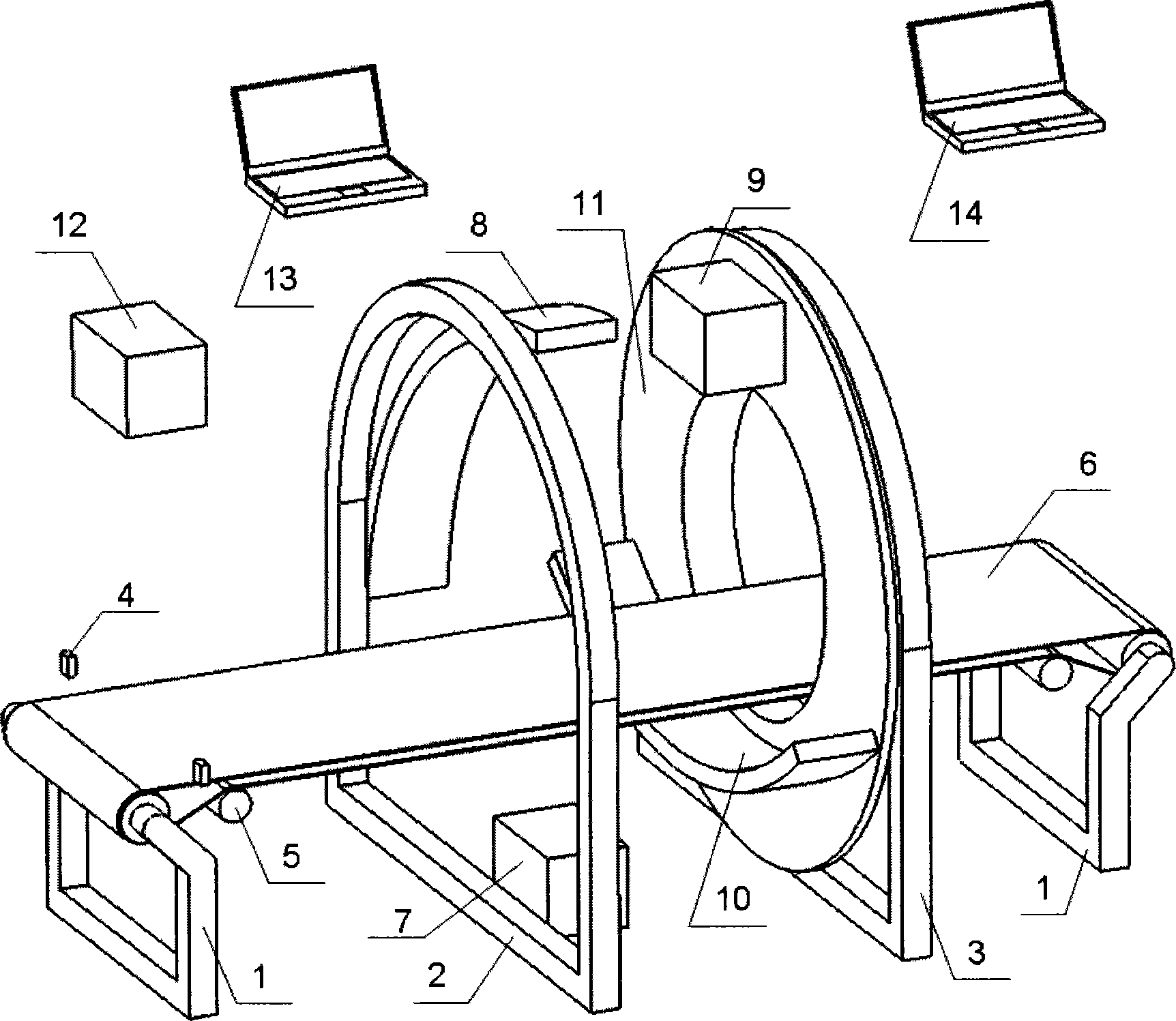
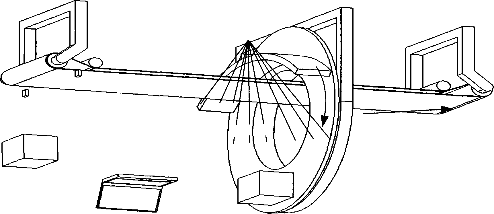
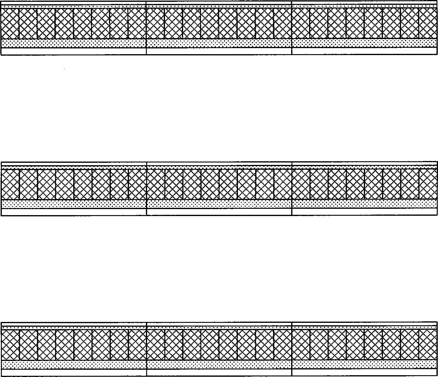
[0028] like figure 1 and 2 As shown in , the inspection system according to the present invention includes: a CT device, the CT device includes: a slip ring, a radiation source connected to the slip ring, a detection device opposite to the radiation source and connected to the slip ring; The conveying device, wherein the detection device includes N rows of detectors, and there is a predetermined interval between two adjacent rows of detectors, wherein N is an integer greater than 1.

[0029] In one embodiment of the present invention, the inspection system may further include a scanning imaging device for obtaining a two-dimensional image, and the CT device and the ...


PUM

PropertyMeasurementUnit
densityaaaaaaaaaa

Abstract

The invention provides an examining system, wherein the system comprises a CT (computed tomography) device which comprises a slip ring, a ray source connected to the slip ring, a detecting device opposite to the ray source and connected to the slip ring, and a transmitting device for transmitting examined objects; when the examined objects are progressed and approached to the plane at which the slip ring is positioned, the examined objects are slowed down for progressing at a low speed, and are accelerated for progressing at a high speed after the ray sources stops emitting rays, wherein the detecting device comprises N lines of detectors; a predetermined interval is reserved between two adjacent lines of detectors; N is an integer greater than one. By utilizing the examining system provided by the invention, the high-speed scan imaging of the CT device is realized, and the CT device and a scan imaging device for obtaining two-dimensional images are possibly used synchronously, so that the defects between the CT device and the scan imaging device are overcome.

Description

[0001] This application is a divisional application of a patent application with the application number 200710176528.4, the title of the invention is "inspection system, inspection method, CT device and detection device", and the application date is October 30, 2007. technical field [0002] The invention relates to an inspection system, an inspection method, a CT device and a detection device. Background technique [0003] In order to solve the scanning speed problem of the CT device, a conventional method is to use multiple rows of detectors, so that multiple rows of data can be collected at the same time each time, such as patent application WO2005 / 119297. However, due to the high cost of detectors, it is not realistic to increase the number of rows significantly. Contents of the invention [0004] The present invention proposes an inspection system, an inspection method, a CT device, and a detection device, wherein the detection device can effectively reduce the number...

Claims


Application Information

Patent Timeline
Patent Type & Authority Patents(China)
IPC IPC(8): G01N23/04G01V5/00
Inventor 张丽陈志强胡海峰李元景刘以农孙尚民张文宇邢宇翔
Owner TSINGHUA UNIV
Why Eureka
Try Eureka