Rail vehicle air conditioning unit using L-shaped condensers

A technology for rail vehicles and air-conditioning units, which is applied in the field of rail vehicle refrigeration systems, can solve the problems of long air-conditioning units, poor heat exchange effect, and large resistance, and achieve the goals of saving head space, improving overall machine efficiency, and reducing overall machine noise Effect

Inactive Publication Date: 2017-08-15
CRRC QINGDAO SIFANG ROLLING STOCK RES INST
View PDF5 Cites 0 Cited by
  • Summary
  • Abstract
  • Description
  • Claims
  • Application Information

AI Technical Summary

Problems solved by technology

Disadvantages of this long and straight condenser: many rows, large resistance, poor heat transfer effect, long dimension required in the length direction, need to occupy the space of other cavities, the length of the air conditioning unit will be longer, and the weight will be heavy
At present, tram air-conditioning units generally use long straight tube-fin condensers, and the overall length is relatively long. Due to the limited space on the top of the vehicle, although it can currently meet the performance requirements of the existing tram air-conditioning system, it is difficult to achieve Requirements for Lighter and Miniaturized Tram Air Conditioning Systems
In the existing tram air-conditioning units, the traditional conventional long straight tube-fin condenser technology has been developed maturely and has been used for a long time. The higher requirements put forward by air conditioning units, so the traditional long straight condenser type is gradually facing challenges

Method used


Image

  • Rail vehicle air conditioning unit using L-shaped condensers
  • Rail vehicle air conditioning unit using L-shaped condensers
  • Rail vehicle air conditioning unit using L-shaped condensers

Examples


Embodiment Construction

[0034] The specific implementation manners of the present invention will be clearly and completely described below in conjunction with the accompanying drawings. Apparently, the embodiments described in the specific implementation are only some of the embodiments of the present invention, rather than all the embodiments. Based on the embodiments of the present invention, all other embodiments obtained by persons of ordinary skill in the art without making creative efforts belong to the protection scope of the present invention.

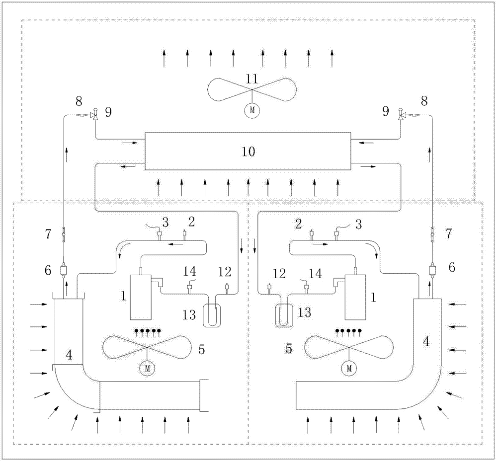
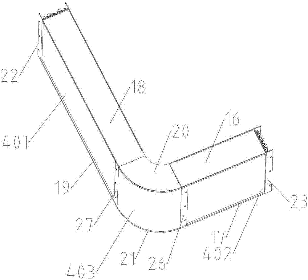
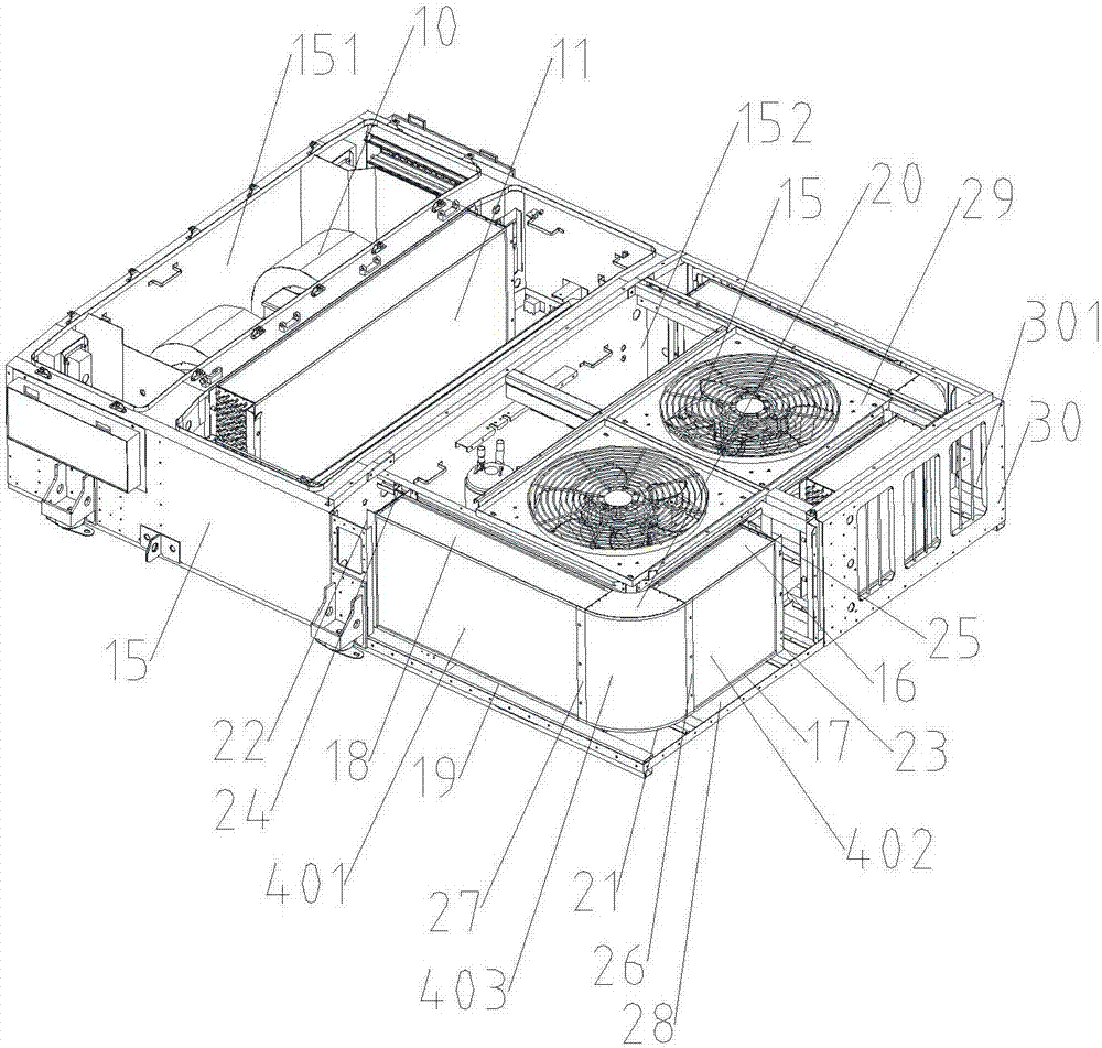
[0035] Such as Figure 1 to Figure 4 As shown, the rail vehicle air-conditioning unit using the L-shaped condenser includes a box body 15, and the box body 15 includes an evaporation chamber 151 and a condensation chamber 152, which are used to install the evaporation unit and the condensation unit respectively. The condensation unit mainly includes a compressor 1, a section Flow device 9, condenser 4 and condensing fan 5, the evaporator unit mainly ...


PUM


Abstract

The rail vehicle air conditioning unit using the L-shaped condenser includes a box body, and the box body includes an evaporation chamber and a condensation chamber, which are respectively used for installing the evaporation unit and the condensation unit; the condensation unit mainly includes a compressor, a throttling device, a condensation A condenser and a condensing fan, the evaporator unit mainly includes an evaporator; it is characterized in that: the condenser is an L-shaped condenser, including an L-shaped condensing fin group composed of multiple sets of L-shaped condensing fins, including mutually perpendicular Condensing fin group I and condensing fin group II, there is an arc-shaped transition fin group between condensing fin group I and condensing fin group II, and the inlet section header and outlet section header are located in the L-shaped fin One side of the vertical end of the sheet group is connected to the inlet header compressor, and the outlet header is connected to the evaporator through a throttling device; the evaporator is connected to the compressor; the railway vehicle air-conditioning unit provided by the invention adopts L type condenser, which meets the development requirements of high efficiency, light weight and small size of railway vehicle air conditioning units.

Description

technical field [0001] The invention belongs to the technical field of rail vehicle refrigeration systems, and relates to a rail vehicle air-conditioning unit, in particular to an rail vehicle air-conditioning unit using an L-shaped condenser. Background technique [0002] As one of the main components of rail vehicles, the air conditioning unit plays a role in ventilation, adjusting the air temperature and humidity in the vehicle, and improving the comfort performance of the vehicle, and plays a key role in the vehicle environmental control system. [0003] The condenser is a key component for heat exchange of the working fluid. The condenser of the existing tram air-conditioning unit is a traditional copper tube-fin structure, usually a long straight tube-fin condenser, placed vertically, and the working fluid is in the The copper tube flows, the air passes outside the copper tube, and the heat exchange is performed through the tube wall and the aluminum fins. Disadvantag...

Claims


Application Information

Patent Timeline
Patent Type & Authority Applications(China)
IPC IPC(8): B61D27/00
CPCB61D27/0072
Inventor 王宏宇韩冰吕艳宗
Owner CRRC QINGDAO SIFANG ROLLING STOCK RES INST
Why Eureka
Try Eureka