Prostate magnet therapy rod assembly and use method thereof

A prostate and magnetic therapy technology, applied in the field of medical equipment, can solve problems such as congestion and poor urination, and cannot effectively relieve the deformation and distortion of the prostate urethra, and achieve the effects of accelerating blood flow, relieving chronic prostatitis, and dilating blood vessels

Pending Publication Date: 2020-05-29
李少华
View PDF0 Cites 0 Cited by
  • Summary
  • Abstract
  • Description
  • Claims
  • Application Information

AI Technical Summary

Problems solved by technology

[0004] Therefore, the technical problem to be solved by the present invention is that the prior art cannot effectively alleviate the deformation and distortion of the urethra of the prostate, congestion and poor urination.

Method used


Image

  • Prostate magnet therapy rod assembly and use method thereof
  • Prostate magnet therapy rod assembly and use method thereof
  • Prostate magnet therapy rod assembly and use method thereof

Examples


Embodiment 1

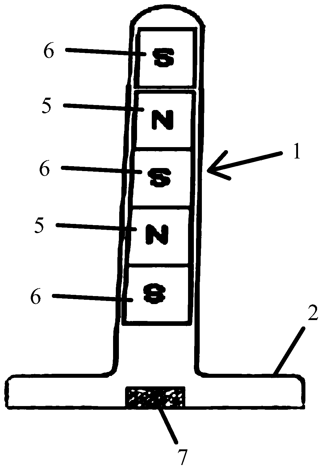
[0047] The prostate magnetic therapy stick assembly provided by this embodiment, such as figure 1 and figure 2 shown, which includes:

[0048] The first magnetic therapy rod 1, the first magnetic therapy rod 1 generates a first magnetic field extending along its length direction, the first magnetic therapy rod 1 is provided with a first limit abutment for limiting the depth of its insertion into the anus part 2, and the plane where the first limit abutment part 2 is located is at an oblique angle to the first magnetic therapy rod 1, and the plane where the first limit abutment part 2 is located and the first magnetic therapy rod The first inclination angle formed by a magnetic therapy rod 1, the angle range of the first inclination angle is: 91 degrees to 95 degrees, and the above-mentioned angles in this embodiment can be 91 degrees, 95 degrees, and 91 degrees and 95 degrees any angle value between; the above-mentioned first magnetic therapy rod 1 includes N-level magnets ...

Embodiment 2

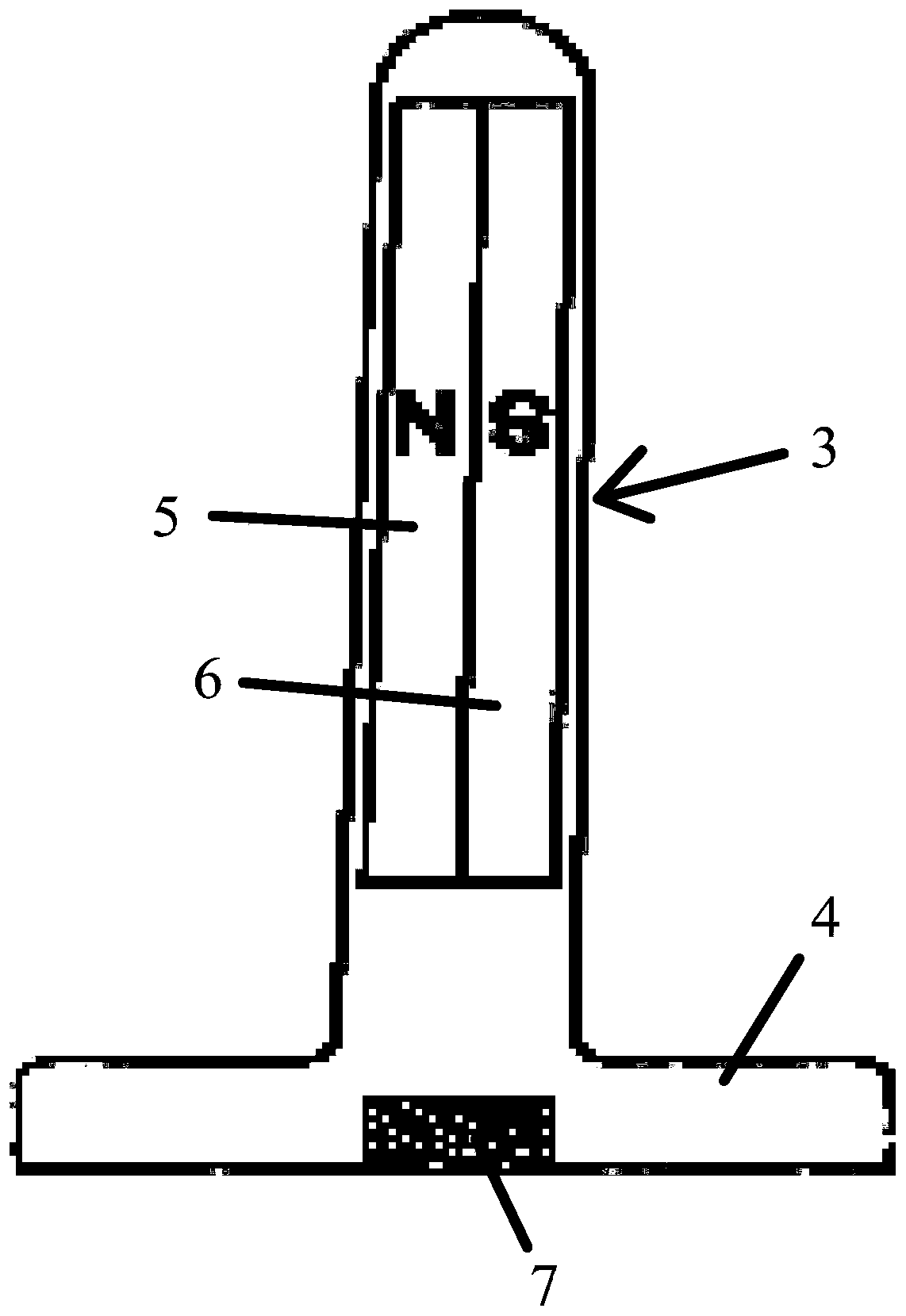
[0062] The difference between this embodiment and embodiment 1 is that

[0063] The first magnetic therapy rod 1, the first magnetic therapy rod 1 generates a first magnetic field extending along its length direction, the first magnetic therapy rod 1 is provided with a first limit abutment for limiting the depth of its insertion into the anus part 2, and the plane where the first limit abutment part 2 is located is at an oblique angle to the first magnetic therapy rod 1, and the plane where the first limit abutment part 2 is located and the first magnetic therapy rod The first inclination angle formed by a magnetic therapy rod 1, the angle range of the first inclination angle is: 10 degrees to 12 degrees, and the above-mentioned angles in this embodiment can be 10 degrees, 12 degrees, and 10 degrees and 12 degrees any angle value between; the above-mentioned first magnetic therapy rod 1 includes N-level magnets 5 and S-level magnets 6 connected end-to-end along the length dire...


PUM


Abstract

The invention discloses a prostate magnet therapy rod assembly and a use method thereof. The prostate magnet therapy rod assembly comprises a first magnet therapy rod and a second magnet therapy rod,wherein the first magnet therapy rod generates a first magnetic field which extends in a length direction of the first magnet therapy rod, a first limiting and abutting part used for limiting the anusinsertion depth of the first magnet therapy rod is arranged on the first magnet therapy rod, and the plane where the first limiting and abutting part is located is at an oblique angle to the first magnet therapy rod; and the second magnet therapy rod generates a second magnetic field which extends in a circumferential direction of the second magnet therapy rod, a second first limiting and abutting part used for limiting the anus insertion depth of the second magnet therapy rod is arranged on the second magnet therapy rod, and the plane where the second limiting and abutting part is located isat an oblique angle to the second magnet therapy rod. Through the first magnet therapy rod and the second magnet therapy rod, blood vessels can be effectively expanded, blood flows can be effectivelyaccelerated, and the problems of deformation and twisting of a urethra of a prostatic part, hyperaemia and dysuria are eased.

Description

technical field [0001] The invention relates to the technical field of medical devices, in particular to a prostate magnetic therapy rod assembly and a usage method thereof. Background technique [0002] Chronic prostatitis refers to chronic inflammation of prostate tissue caused by various etiologies, and is the most common disease in urology. Pain symptoms are mainly manifested in the pain radiating to the surrounding tissues centered on the prostate, and are often seen in pain, swelling or discomfort in the scrotum, testis, lower abdomen, perineum, lumbosacral, and medial thigh. Its course of disease of chronic prostatitis is slow, protracted, seriously affects people's quality of life. [0003] The predisposing factors of prostatitis are: benign prostatic hyperplasia or stones in the prostate. Prostatic hyperplasia or stones in the prostate will deform and distort the urethra of the prostate, cause congestion and poor urination, and reduce the immune ability of the ure...

Claims


Application Information

Patent Timeline
Patent Type & Authority Applications(China)
IPC IPC(8): A61N2/08
CPCA61N2/004A61N2/06
Inventor 梁雪松
Owner 李少华
Why Eureka
Try Eureka