
Sliding mode control method for optimizing vehicle yawing dynamic performance under all working conditions

A technology of dynamic performance and control method, which is applied in the field of yaw dynamic sliding mode control, the sliding mode control field that optimizes vehicle yaw dynamic performance, and can solve the problem of slow vehicle steering response, lack of yaw dynamic control technology, and yaw rate overshoot. Large and other problems, to achieve the effect of optimizing dynamic response performance

Active Publication Date: 2020-05-29
HARBIN INST OF TECH
View PDF22 Cites 4 Cited by
  • Summary
  • Abstract
  • Description
  • Claims
  • Application Information

AI Technical Summary

Problems solved by technology

[0002] The vehicle has the following characteristics when turning: 1. Under normal working conditions, the yaw dynamics show over-damping or large damping characteristics; under extreme working conditions, the yaw dynamics show under-damping characteristics; Dynamic over-damping or large damping characteristics lead to slow yaw response, making the vehicle steering response sluggish, under extreme conditions, yaw dynamic under-damping characteristics lead to large overshoot of yaw rate, affecting the yaw stability of the vehicle
[0003] Vehicle yaw stability control is an important active safety system to ensure vehicle driving safety, but the existing yaw stability control strategy mainly focuses on the tracking accuracy of yaw rate, which belongs to yaw stability performance, or discusses yaw for specific limit conditions Rate dynamic control performance, lack of yaw dynamic control technology under all working conditions

Method used


Image

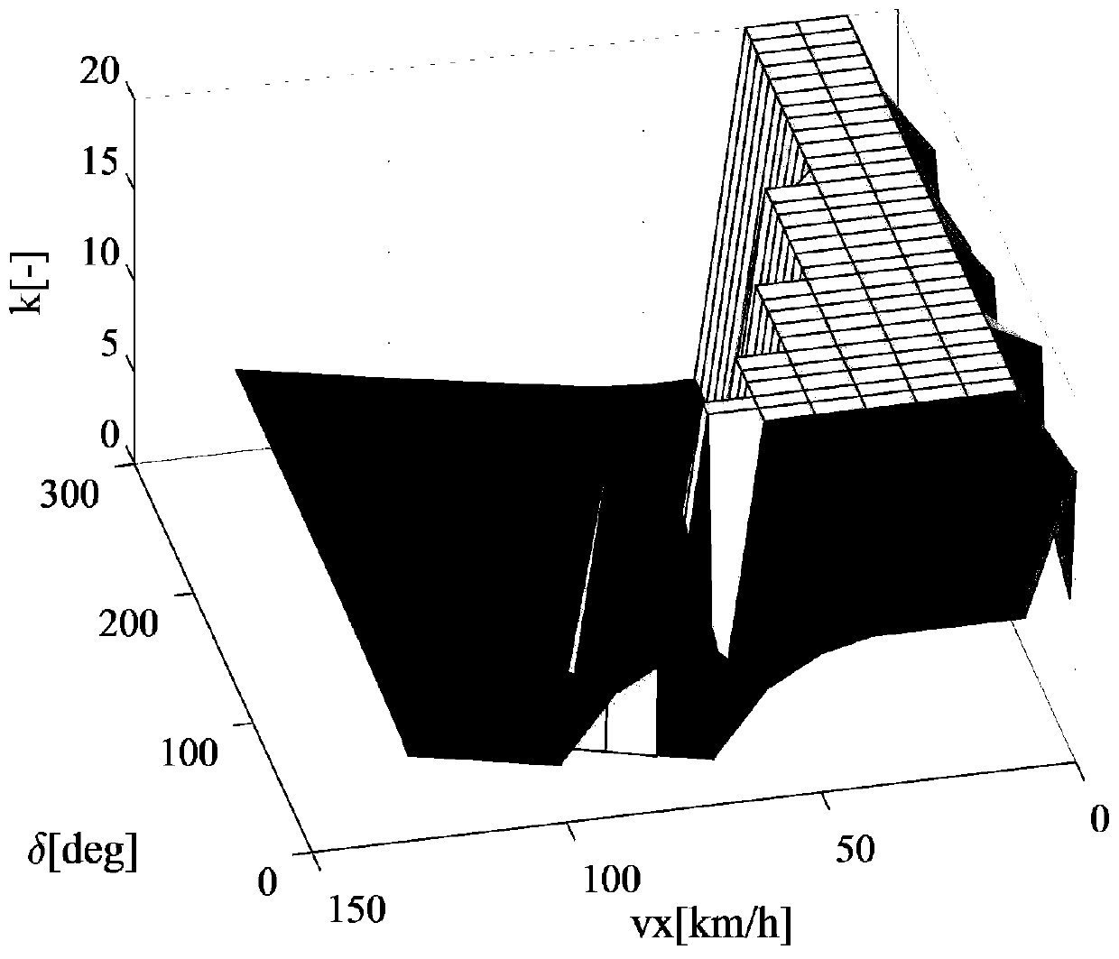
  • Sliding mode control method for optimizing vehicle yawing dynamic performance under all working conditions
  • Sliding mode control method for optimizing vehicle yawing dynamic performance under all working conditions
  • Sliding mode control method for optimizing vehicle yawing dynamic performance under all working conditions

Examples


Embodiment Construction

[0054] The technical solutions in the present invention will be clearly and completely described below in conjunction with the accompanying drawings in the embodiments of the present invention. Obviously, the described embodiments are only part of the embodiments of the invention, not all of them. Based on the present invention All other embodiments obtained by persons of ordinary skill in the art without creative efforts, all belong to the scope of protection of the present invention.

[0055] The invention discloses a sliding mode control method for optimizing vehicle yaw dynamic performance under all working conditions, comprising the following steps:

[0056] Step 1: Establish a two-degree-of-freedom vehicle dynamics equation that can characterize vehicle yaw rate and lateral velocity dynamics,

[0057]

[0058]

[0059] Among them, m is the mass of the vehicle, I z is the moment of inertia of the vehicle around the z-axis, l f is the distance from the center of ma...


PUM


Abstract

The invention discloses a sliding mode control method for optimizing vehicle yawing dynamic performance under all working conditions, and relates to a yawing dynamic sliding mode control method. The method comprises steps of establishing a two-degree-of-freedom vehicle kinetic equation capable of representing the vehicle yaw rate and the lateral speed dynamic state; designing a sliding mode surface and a sliding mode control law expression for ensuring the stability of a closed-loop system according to the expected yaw rate, the lateral speed and the roll angle speed; providing an index for describing yaw response dynamic performance through yaw rate overshoot and adjustment time; giving a mathematical expression for calculating yaw rate overshoot and adjusting time; and solving an optimization problem to obtain a sliding mode control law parameter which enables the yawing dynamic state to be optimal. By designing a sliding mode controller and adjusting sliding mode surface parameters,yaw rate overshoot and adjustment time adjustment are achieved, the defects of existing yaw stability control are overcome, and the sliding mode control method capable of guaranteeing optimization ofvehicle yaw dynamic response performance under all working conditions is provided.

Description

technical field [0001] The invention relates to a yaw dynamic sliding mode control method, in particular to a sliding mode control method for optimizing vehicle yaw dynamic performance under all working conditions, belonging to the field of vehicle drive control. Background technique [0002] The vehicle has the following characteristics when turning: 1. Under normal working conditions, the yaw dynamics show over-damping or large damping characteristics; under extreme working conditions, the yaw dynamics show under-damping characteristics; The dynamic over-damping or large damping characteristics lead to slow yaw response, which makes the steering response of the vehicle sluggish. Under extreme conditions, the dynamic under-damping characteristics of the yaw lead to a large overshoot of the yaw rate, which affects the yaw stability of the vehicle. [0003] Vehicle yaw stability control is an important active safety system to ensure vehicle driving safety, but the existing ya...

Claims


Application Information

Patent Timeline
Patent Type & Authority Applications(China)
IPC IPC(8): B60W30/02B60W40/10
CPCB60W30/02B60W40/10
Inventor 周洪亮贾凤娇刘志远
Owner HARBIN INST OF TECH
Learn More