Projection Screens and Projection Systems

A projection screen and projection technology, applied in the field of projection systems, can solve the problems that the screen cannot be shared by telephoto projectors and ultra-short-focus projectors, increase user cost, reduce space utilization, etc., and achieve a good effect against ambient light. , Improve contrast, increase the effect of horizontal viewing angle

Active Publication Date: 2022-04-22
APPOTRONICS CORP LTD
View PDF6 Cites 0 Cited by
  • Summary
  • Abstract
  • Description
  • Claims
  • Application Information

AI Technical Summary

Problems solved by technology

[0006] As can be seen from the above, since the telephoto projector and the ultra-short-focus projector need screens with different optical structures, the screens in the prior art cannot be shared by the telephoto projector and the ultra-short-focus projector, which increases the use of cost, reduced space utilization

Method used


Image

  • Projection Screens and Projection Systems
  • Projection Screens and Projection Systems
  • Projection Screens and Projection Systems

Examples


no. 1 example

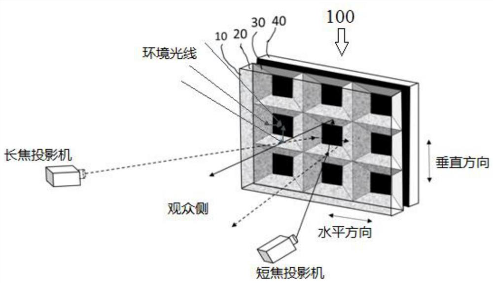
[0054] 1.1 Structure overview

[0055] image 3 is a schematic diagram showing the structure of the projection screen according to the first embodiment of the present invention. Such as image 3 As shown in , the projection screen 100 includes a light diffusing layer 10 , a substrate layer 20 , a reflective layer 30 and a light absorbing layer 40 arranged sequentially from the viewer side (ie, the incident side of projection light). The reflective layer 30 is provided with a plurality of microstructure units, and these microstructure units are arranged in a two-dimensional manner to form a microstructure unit array. The microstructure unit may be formed on the side of the substrate layer 20 facing away from the viewer by coating resin on the roll and UV curing process. In other words, the reflective layer 30 and the substrate layer 20 may be integrally formed. The light can pass through the light diffusing layer 10 and the substrate layer 20 in sequence to reach the reflec...

no. 2 example

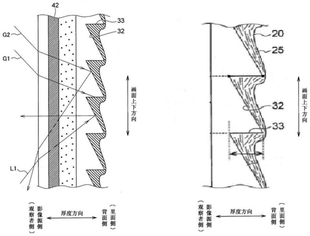
[0110] The following will refer to Figure 21 to Figure 25 A projection screen according to a second embodiment of the present invention is explained.

[0111] Figure 21 is a perspective view showing a projection screen according to a second embodiment of the present invention. Such as Figure 21 As shown in , the projection screen 200 includes a light diffusing layer 10 , a substrate layer 20 , a reflective layer 30 and a light absorbing layer 40 arranged sequentially from the viewer side (ie, the incident side of projection light). The reflective layer 30 is provided with a plurality of microstructure units, and these microstructure units are arranged in a two-dimensional manner to form a microstructure unit array. The difference between the projection screen 200 of the second embodiment and the projection screen 100 of the first embodiment mainly lies in the specific structure of the reflective microstructure unit. Such as Figure 21 and Figure 22 As shown in , the ...


PUM


Abstract

The invention discloses a projection screen and a projection system. The projection screen includes a reflective layer arranged in sequence from the incident side of the projected light and a light absorbing layer for absorbing light. The reflective layer includes a plurality of microstructure units, and each microstructure unit includes first and second obliquely opposite in the first direction. plane and obliquely opposite third and fourth planes in the second direction, the inclination angles of the first and second planes with respect to the screen plane of the projection screen are set so that projections incident with a first angle of incidence within a first angle range At least a portion of the light is reflected at the first and second planes and eventually enters the field of view of the viewer, and the third and fourth planes are set at an inclination angle relative to the screen plane of the projection screen such that the second At least a part of the projection light incident at the second incident angle within the range of angles is reflected at the third and fourth planes and finally enters the viewer's field of view, and the first incident angle is smaller than the second incident angle.

Description

technical field [0001] The present invention relates to projection screens and projection systems. In particular, the present invention relates to a projection screen with high contrast that can be applied to both a telephoto projector and an ultra-short throw projector and a projection system using the same. Background technique [0002] In recent years, with the continuous improvement of the brightness of projectors, the advantages of projection display systems in large-scale home theater applications have begun to emerge. Compared with LCD TVs and OLED TVs, the projection display system is small in size, easy to install, and can easily realize a display screen larger than 100 inches, and the price of the whole system is relatively low. [0003] According to different throw ratios, projectors can be divided into telephoto projectors and short-focus projectors. Traditional projectors are called telephoto projectors, which usually require a distance of more than 3 meters t...

Claims


Application Information

Patent Timeline
Patent Type & Authority Patents(China)
IPC IPC(8): G03B21/60G02B5/02G02B5/124
CPCG03B21/60G02B5/0221G02B5/0226G02B5/124G03B21/602G02B5/003G02B2207/123G02B19/0019
Inventor 孙微王霖唐泽达胡飞李屹
Owner APPOTRONICS CORP LTD
Why Eureka
Try Eureka