Machine head assemblies of ironing sheet machine and ironing sheet machine

A machine head and assembly technology, applied in the field of embroidery machines, can solve problems such as inability to mesh smoothly, gear damage, etc., and achieve the effect of simplifying the waste collection structure

Active Publication Date: 2020-06-19
ZHEJIANG XINSHENG SEWING EQUIP
View PDF12 Cites 11 Cited by
  • Summary
  • Abstract
  • Description
  • Claims
  • Application Information

AI Technical Summary

Problems solved by technology

However, there may be some problems in the gear transmission. The main reason is that the sheet-feeding driven gear will rotate due to the vibration of the machine operation, which will cause the misalignment of the sheet-feeding driving gear and the sheet-feeding driven gear during the color change process, and cannot mesh smoothly, causing the gear or other damage

Method used


Image

  • Machine head assemblies of ironing sheet machine and ironing sheet machine
  • Machine head assemblies of ironing sheet machine and ironing sheet machine
  • Machine head assemblies of ironing sheet machine and ironing sheet machine

Examples


Embodiment Construction

[0027] The following will clearly and completely describe the technical solutions in the embodiments of the present invention with reference to the accompanying drawings in the embodiments of the present invention. Obviously, the described embodiments are only some, not all, embodiments of the present invention. The following description of at least one exemplary embodiment is merely illustrative in nature and in no way taken as limiting the invention, its application or uses. Based on the embodiments of the present invention, all other embodiments obtained by persons of ordinary skill in the art without creative efforts fall within the protection scope of the present invention.

[0028] Those skilled in the art can understand that, under the condition of no conflict, the features in the following embodiments and implementation manners can be combined with each other.

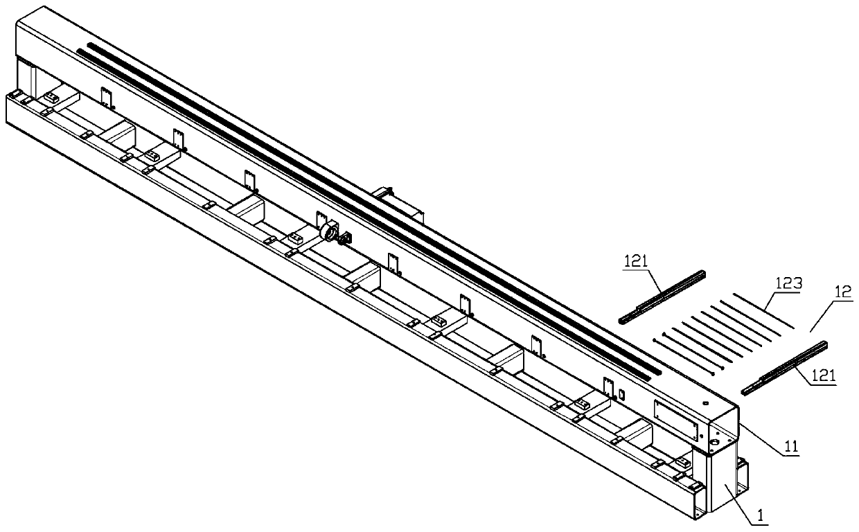
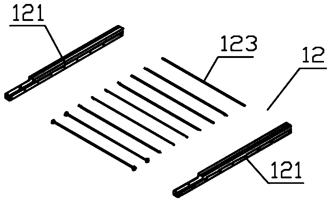
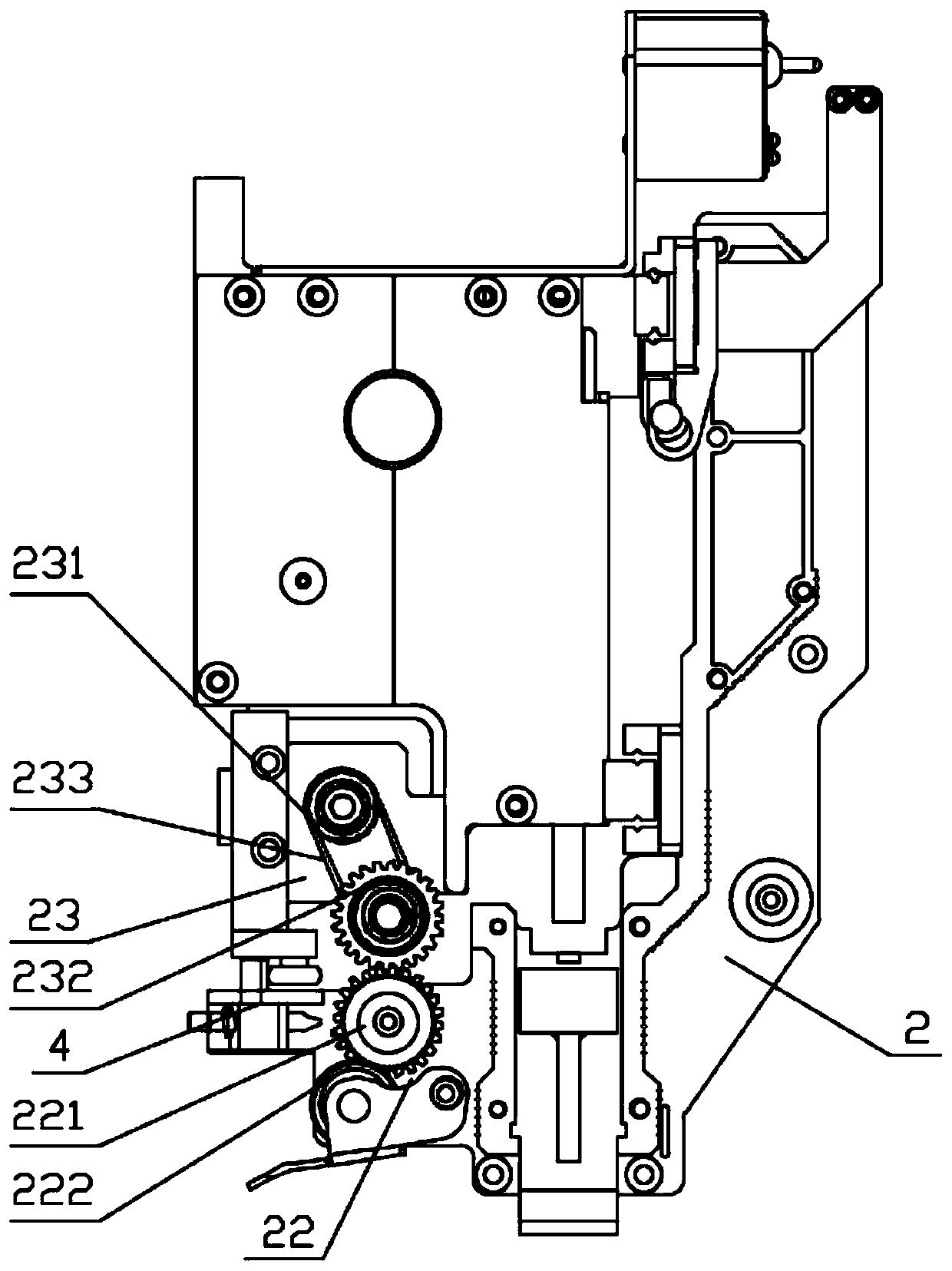
[0029] refer to Figure 1 to Figure 6 As shown, the ironing machine head assembly includes the ironing mach...


PUM


Abstract

The present invention discloses machine head assemblies of an ironing sheet machine and the ironing sheet machine. The ironing sheet machine comprises an ironing sheet machine shell assembly and at least two ironing sheet machine head assemblies arranged side by side; each ironing sheet machine head assembly comprises a machine head shell and a sheet conveying roller set mounted on the machine head shell; each sheet conveying roller set comprises drive rollers; the ironing sheet machine shell assembly comprises a machine shell and a sheet conveying motor mounted on the machine shell; the sheetconveying motor drives the drive rollers to rotate through a sheet conveying transmission mechanism; the sheet conveying transmission mechanism comprises a sheet conveying drive gear and a sheet conveying driven gear which are meshed; the sheet conveying driven gear is connected with the drive rollers; the ironing sheet machine further comprises a sheet conveying driven gear self-locking mechanism for locking the sheet conveying driven gear after color change; and the sheet conveying driven gear self-locking mechanism comprises a self-locking push rod which can be clamped in a driven gear tooth groove. A plate-by-plate waste collection structure of a conventional ironing sheet machine is greatly simplified and the sheet conveying driven gear is prevented from rotating by vibration due tomachine operation.

Description

technical field [0001] The invention belongs to the technical field of embroidery machines, and in particular relates to an ironing machine. Background technique [0002] In the prior art, the waste collection of the ironing belt is carried out through the winding of the waste collection plate driven by the waste collection motor, and a waste collection frame, a waste collection motor and a corresponding transmission mechanism need to be provided. In addition, since one machine head has ironing sheets of various specifications (colors), a waste collection tray needs to be provided corresponding to each specification of ironing sheet waste, which results in a complicated structure and high cost of the waste collection device. Moreover, after the waste collection tray is full, it needs to be disassembled and replaced, and simultaneously there will be an extra step of removing the waste material on the ironing sheet on the waste collection tray, which increases labor intensity ...

Claims


Application Information

Patent Timeline
Patent Type & Authority Applications(China)
IPC IPC(8): D05C7/08D05C13/00
CPCD05C7/08D05C13/00
Inventor 王海江田桂郁洪晓峰
Owner ZHEJIANG XINSHENG SEWING EQUIP
Why Eureka
Try Eureka