Automatic feeding article storage rack

A technology for item storage and automatic loading, applied to shelves, household appliances, applications, etc., can solve problems such as high labor intensity and cost, poor material identification and management ability, and complex types, so as to improve flexibility, reliability, and good quality. The effect of bearing positioning capacity and high degree of operation automation

Inactive Publication Date: 2020-06-26
韩亮
View PDF0 Cites 2 Cited by
  • Summary
  • Abstract
  • Description
  • Claims
  • Application Information

AI Technical Summary

Problems solved by technology

[0002] In large-scale warehouses such as logistics warehousing, it is necessary to use a large number of shelves to classify and store items. Although the current shelves can meet the needs of use, due to the large amount of material storage and complex types, the current storage of materials When picking operations, on the one hand, there is poor ability to identify and manage materials, and on the other hand, the efficiency of access operations is low and the labor intensity and cost are relatively high. As a result, the current warehousing operations cannot meet the needs of actual material access and management operations. In response to this problem, at present, material access is mainly carried out by means of electronic tags, automatic access robots and other equipment. Although the efficiency of material access operations can be improved to a certain extent and the labor intensity is reduced, the use, operation and The maintenance cost is relatively high, and it is difficult to be fully popularized and applied. At the same time, the current shelves for material storage still have relatively fixed structural defects to varying degrees, which leads to poor versatility of the shelves and cannot effectively meet the needs of different material storage operations. Therefore, for This problem urgently needs to develop a kind of brand-new article storage frame structure, to meet the needs of actual use

Method used


Image

  • Automatic feeding article storage rack

Examples


Embodiment Construction

[0014] In order to make the technical means, creative features, objectives and effects of the present invention easy to understand, the present invention will be further explained below in conjunction with specific embodiments.

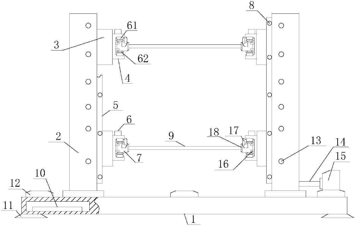
[0015] Such as figure 1 The described storage rack for automatically feeding articles includes a bearing base 1, a bearing column 2, a horizontal beam 3, a horizontal guide rail 4, a vertical guide rail 5, a linear motor 6, a slider 7, an in-position sensor 8, and a bearing plate 9 and control circuit 10, the carrying base 1 is a closed cavity structure with a rectangular cross section, at least four positioning mechanisms 11 are uniformly distributed on the lower surface of the supporting base 1, at least four supporting pillars 2 are uniformly distributed on the upper surface, and each supporting pillar 2 It is evenly distributed around the axis of the bearing base 1 and vertically distributed to the upper surface of the bearing base 1. At least four h...


PUM


Abstract

The invention relates to an automatic feeding article storage rack. The rack comprises a bearing base, bearing stand columns, a horizontal cross beam, a horizontal guide rail, a vertical guide rail, alinear motor, sliding blocks, in-place sensors, a bearing plate and a control circuit. The at least bearing stand columns are evenly distributed on the upper surface of the bearing base. The horizontal beams are installed on the inner side surfaces of the bearing stand columns. The vertical guide rail is mounted on the inner side surface of the bearing column; the horizontal guide rail is mountedon the inner side of the horizontal beam; the in-place sensors are evenly distributed on the side surfaces of the horizontal guide rail and the vertical guide rail, the linear motor stators are embedded in the inner side faces of the horizontal guide rail and the vertical guide rail respectively, the linear motor rotors are embedded in the side surfaces of the sliding blocks, the sliding blocks are in sliding connection with the horizontal guide rail and the vertical guide rail, and the side surface of the bearing plate is connected with the sliding blocks. The automatic feeding article storage rack has good bearing and positioning capacity, the structure of the goods shelf can be effectively and flexibly adjusted according to the material structure while materials are borne and placed, and the requirements of different material storage operations are met.

Description

Technical field [0001] The invention relates to a shelf equipment, specifically a storage rack for automatic loading articles. Background technique [0002] In large warehouses such as logistics warehousing, it is necessary to use a large number of shelves to classify and store items. Although the currently used shelves can meet the needs of use, due to the large amount of material storage and the complex types, the materials are currently being stored. When taking operations, on the one hand, there is a poor ability to identify and manage materials, on the other hand, the efficiency of storage and retrieval operations is low, and labor intensity and costs are relatively high, which causes the current warehousing operations to fail to meet the needs of actual storage and management of materials. In response to this problem, the current material access is mainly through the use of electronic tags, automatic access robots and other equipment. Although the efficiency of material acc...

Claims


Application Information

Patent Timeline
Patent Type & Authority Applications(China)
IPC IPC(8): A47F1/04
CPCA47F1/04
Inventor 韩亮
Owner 韩亮
Why Eureka
Try Eureka