An automatic opening type air pressure balance hole structure for packaging boxes
A technology of air pressure balance and automatic opening, which is applied in the directions of packaging, transportation, packaging, and cover, and can solve the problems of difficult to achieve automatic balance adjustment of packaging box pressure.
- Summary
- Abstract
- Description
- Claims
- Application Information
AI Technical Summary
Problems solved by technology
Method used
Image
Examples
Embodiment 1
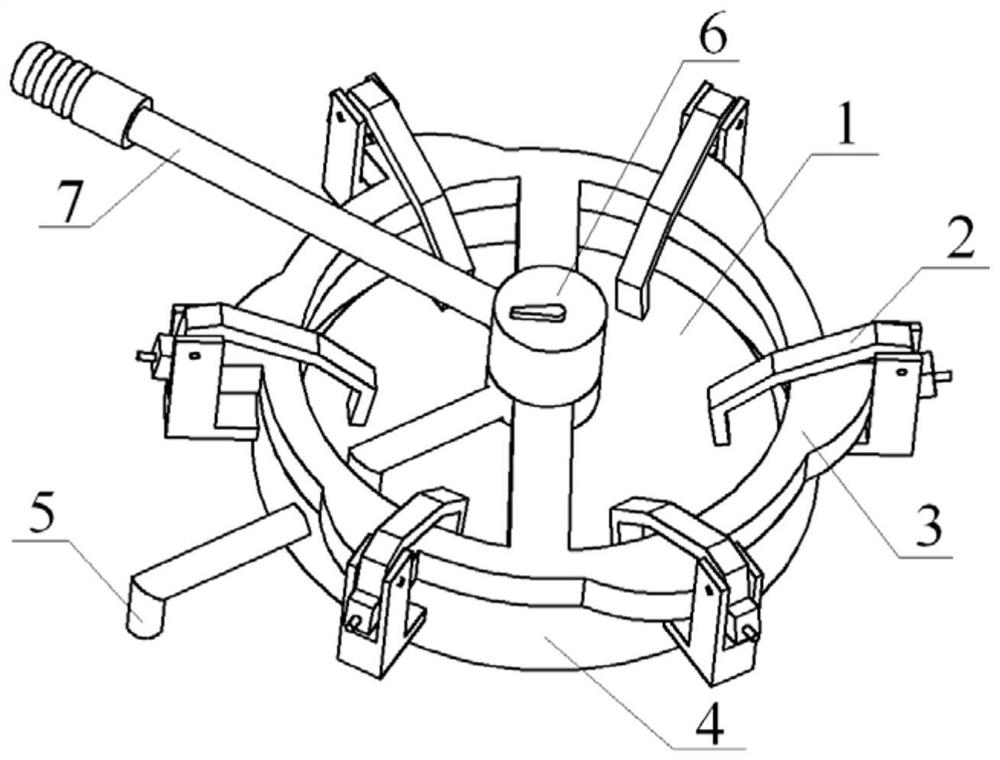
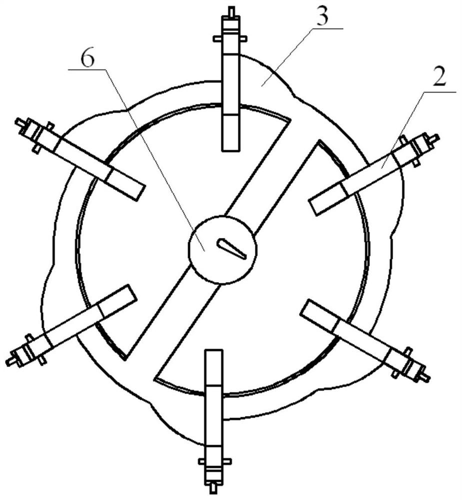
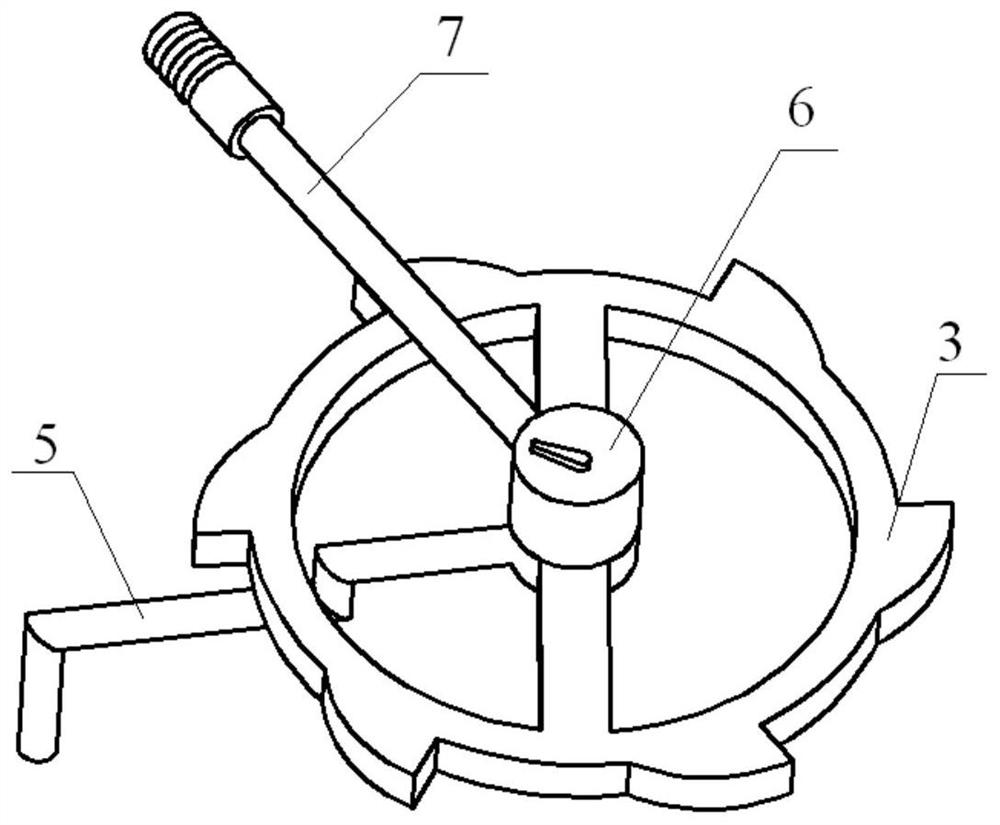
[0036] see Figure 1-8 , the present invention provides a technical solution: an automatic opening type air pressure balance hole structure for packaging boxes, including an air pressure balance hole baffle plate 1, a clamping mechanism 2, a special-shaped cam 3, a bracket 4, a pressure safety valve 5, and a ratchet limiter Mechanism 6 and packing case air pressure balance port 13, the top of packing case air pressure balance port 13 is provided with support 4, and the top of the outer end surface of support 4 is fixedly connected with multiple groups of L-shaped frames distributed in a circular array, and multiple groups of L-shaped frames A clamping mechanism 2 is installed on the inner side of the vertical end. The side of the clamping mechanism 2 close to the bracket 4 is fixedly connected with a horizontally distributed thimble 9 . A pressure safety valve 5 is installed in the middle of the outer end surface of the bracket 4 . A special-shaped cam 3 is installed under the...
Embodiment 2
[0038] Specifically, such as figure 1 , Image 6 with Figure 7 As shown, the air pressure balance hole baffle plate 1 has a disc-shaped structure, and the air pressure balance hole baffle plate 1 and the bracket 4 form a clearance fit. The selection of the clearance fit method facilitates the gas inside the packing box to pass through the air pressure balance hole baffle plate 1 and the bracket 4. The air pressure balance hole baffle plate 1 is embedded with a sealing ring 12 on the outer periphery of the bottom. The setting of the sealing ring 12 improves the sealing performance of the connection between the air pressure balance hole baffle plate 1 and the bracket 4.
Embodiment 3
[0040] Specifically, such as figure 1 , figure 2 , Figure 4 with Figure 5 As shown, the outside of the clamping mechanism 2 is fixedly connected with a fixed limit rod 8 that runs through the L-shaped frame, wherein the inside of the L-shaped frame is located outside the fixed limit rod 8 and has an opening 10 on the bracket, and the fixed limit rod 8 And the setting of the opening 10 on the bracket facilitates the installation process between the clamping mechanism 2 and the L-shaped frame on the bracket 4, and facilitates the vertical rotation adjustment and limit processing of the clamping mechanism 2 at the same time. The top of the bracket 4 is located at the special-shaped The bottom of the cam 3 is equipped with multiple sets of support guide rails 11 distributed in a circular array, and the upper end faces of the multiple sets of support guide rails 11 are fitted with the lower end surfaces of the special-shaped cam 3. The arrangement of the support guide rails 11...
PUM
 Abstract
Description
Claims
Application Information
 - R&D
- Intellectual Property
- Life Sciences
- Materials
- Tech Scout
- Unparalleled Data Quality
- Higher Quality Content
- 60% Fewer Hallucinations
Browse by: Latest US Patents, China's latest patents, Technical Efficacy Thesaurus, Application Domain, Technology Topic, Popular Technical Reports.
© 2025 PatSnap. All rights reserved.Legal|Privacy policy|Modern Slavery Act Transparency Statement|Sitemap|About US| Contact US: help@patsnap.com


