Fitness equipment LED electronic watch

An electronic watch and fitness equipment technology, applied in the field of fitness equipment, can solve problems such as affecting people's fitness experience, no display of electronic instruments, poor contact, etc., so as to avoid the problem of poor contact, improve the display effect, and achieve the effect of stability.

Pending Publication Date: 2020-07-03
XIAMEN ZLINK ELECTRONICS TECH CO LTD
View PDF0 Cites 0 Cited by
  • Summary
  • Abstract
  • Description
  • Claims
  • Application Information

AI Technical Summary

Problems solved by technology

Therefore, when the panel 3' is deformed or the screws are loosened, the positions of the LCD display 2' and the conductive adhesive strip 4' will shift, causing poor contact between the LC

Method used


Image

  • Fitness equipment LED electronic watch
  • Fitness equipment LED electronic watch
  • Fitness equipment LED electronic watch

Examples


Embodiment Construction

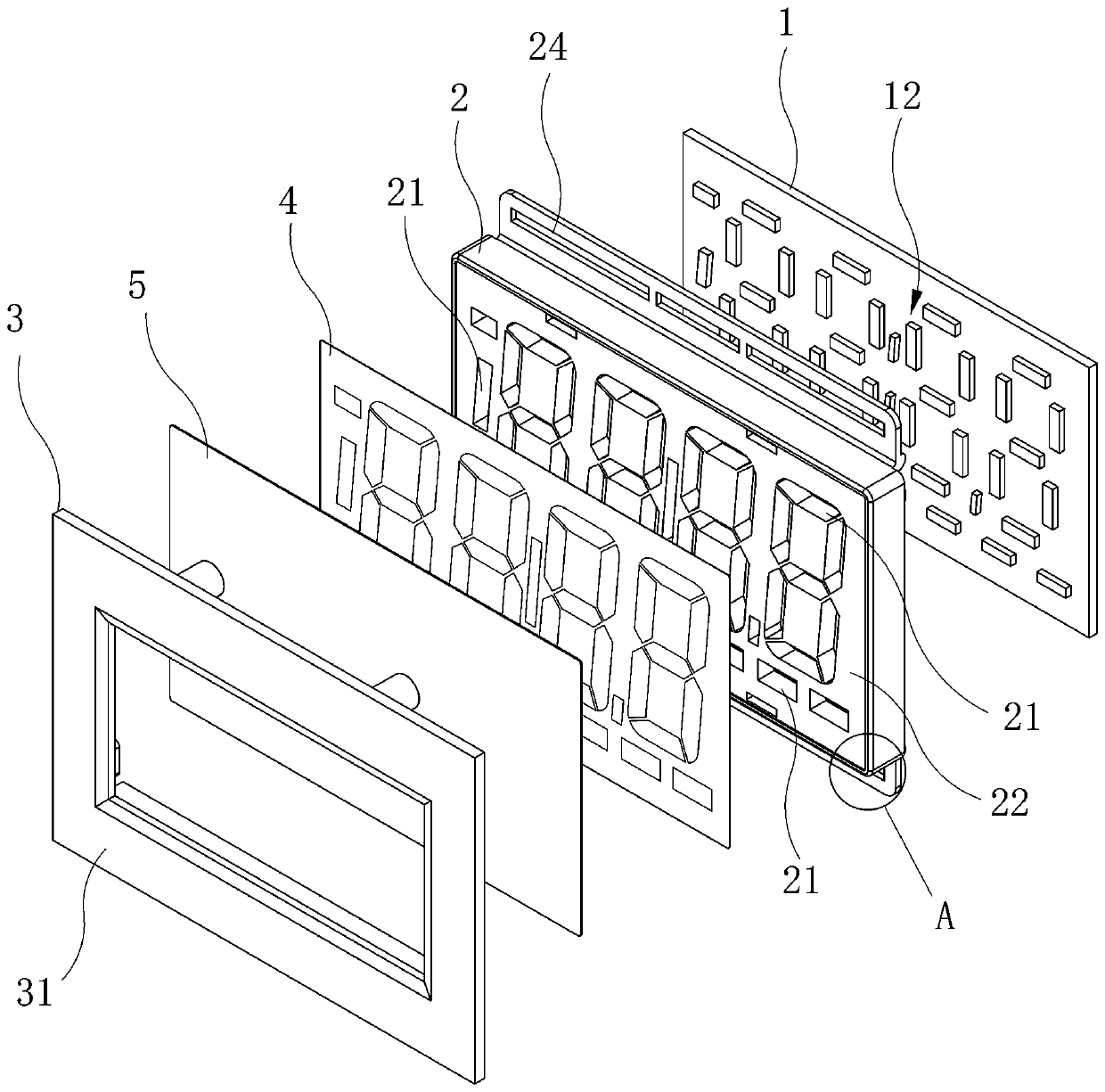
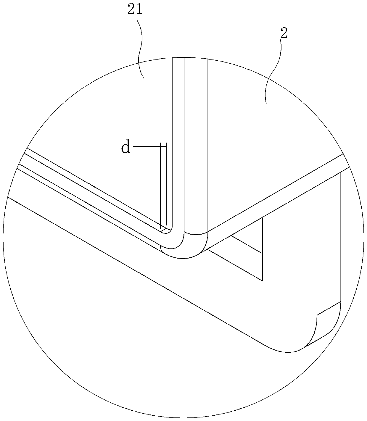
[0027] like Figure 2 to Figure 4 As shown, the present invention discloses an LED electronic watch for fitness equipment, which includes a PCB board 1 , a bracket 2 and a panel 3 . The front surface of the PCB board 1 is provided with a display module 12 composed of a plurality of LEDs, the bracket 2 is provided with a plurality of first grooves 21 penetrating the bracket 2 , and the LEDs fit in the first grooves 21 . A diffusion film 4 and a translucent plate 5 are sandwiched between the panel 3 and the bracket 2 , and the diffusion film 4 and the translucent plate 5 are pressed against the front surface of the bracket 2 in sequence.

[0028] In the present invention, the LED used for display and the PCB board 1 used for controlling the LED display are directly welded together to form a whole, which realizes the stability of the connection of the display part of the electronic watch, and effectively avoids the problem of poor contact caused by external reasons. , which impr...


PUM


Abstract

The invention relates to a fitness equipment LED electronic watch, which comprises a PCB, a support and a panel, and is characterized in that the PCB is connected to the back surface of the support, and the panel is locked to the front surface of the support; a display module composed of a plurality of LED lamps is arranged on the front face of the PCB, a plurality of first grooves penetrating through the support are formed in the support, and the LED lamps are arranged in the first grooves in a matched mode. A diffusion film and a semitransparent plate are clamped between the panel and the support and sequentially abut against the front face of the support in a pressing mode. The display effect of the electronic watch is improved, the situation that the display effect of the electronic watch is affected due to deformation of the panel and loosening of screws is avoided, and the fitness experience of people is improved.

Description

technical field [0001] The invention relates to the field of fitness equipment, in particular to an LED electronic watch for fitness equipment. Background technique [0002] At present, the electronic instruments of fitness equipment generally use LCD screen for display, and its structure is as follows figure 1 shown. The existing electronic instrument includes a PCB board 1', a panel 3' and an LCD display screen 2', the panel 3' and the PCB board 1' are locked by screws, and the LCD display screen 2' and the EVA rubber strip 5' are clamped on the panel. 3' and the PCB board 1', and electrically connected to the PCB board 1' through the conductive adhesive strip 4'. Therefore, when the panel 3' is deformed or the screws are loosened, the positions of the LCD display screen 2' and the conductive adhesive strip 4' will be shifted, resulting in poor contact between the LCD display screen 2' and the PCB board 1', thus causing the electronic meter There are problems such as no...

Claims


Application Information

Patent Timeline
IPC IPC(8): G09F9/33G09F9/302
CPCG09F9/3023G09F9/33
Inventor 赵科锋
Owner XIAMEN ZLINK ELECTRONICS TECH CO LTD
Why Eureka
Try Eureka