
Printing recognition device and coat-printing and data recognition method based on infrared coding

A technology of identification device and data identification, applied in printing device, printing and other directions, can solve problems such as difficult to achieve, and achieve the effect of compact structure, convenient integration, and easy-to-use cost.

Pending Publication Date: 2020-07-14
李泰明
View PDF2 Cites 0 Cited by
  • Summary
  • Abstract
  • Description
  • Claims
  • Application Information

AI Technical Summary

Problems solved by technology

Therefore, in reality, it is difficult to achieve the invention purpose of distinguishing different papers.

Method used


Image

  • Printing recognition device and coat-printing and data recognition method based on infrared coding
  • Printing recognition device and coat-printing and data recognition method based on infrared coding
  • Printing recognition device and coat-printing and data recognition method based on infrared coding

Examples


Embodiment 1

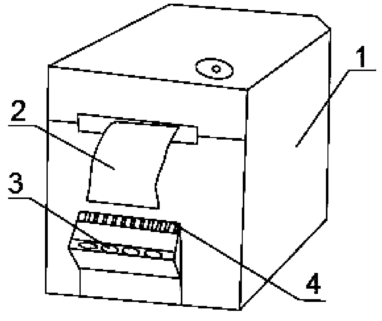
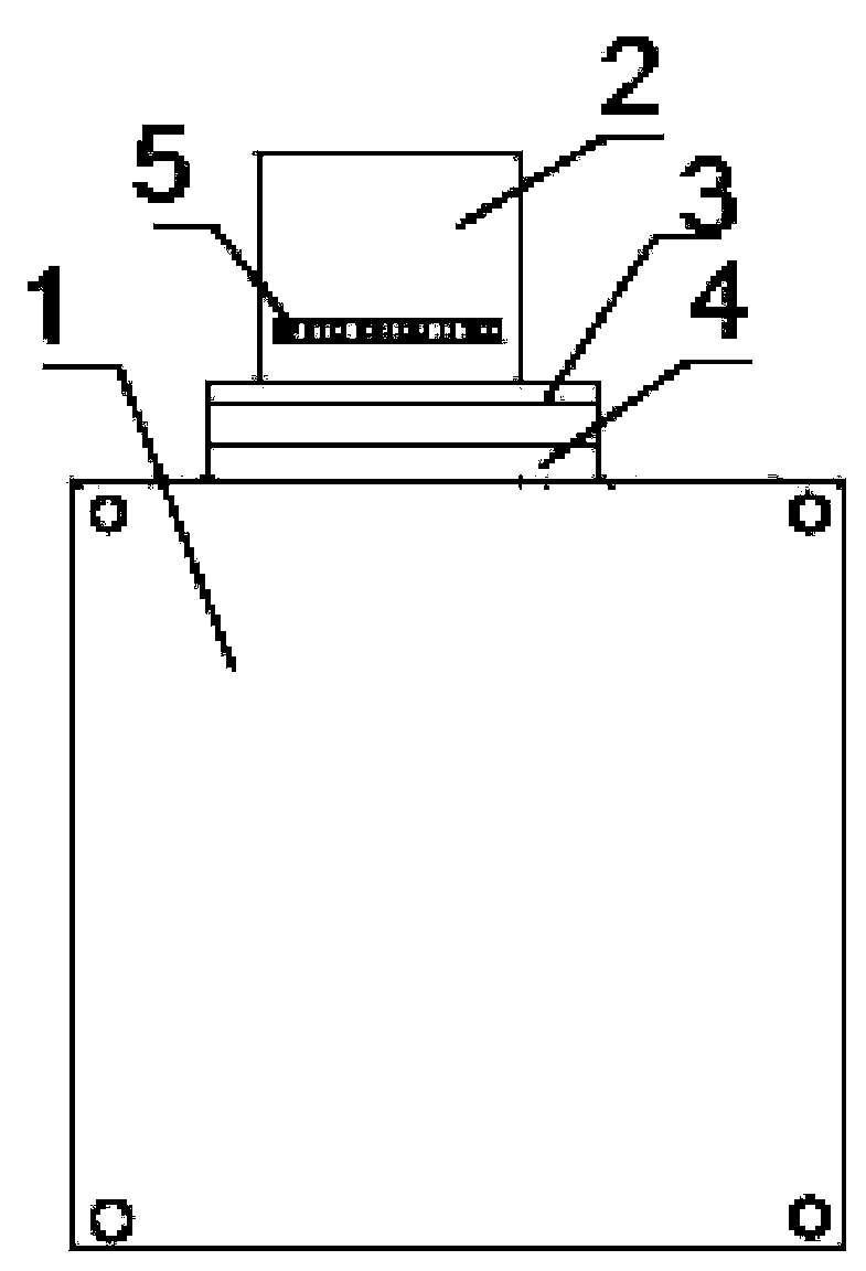
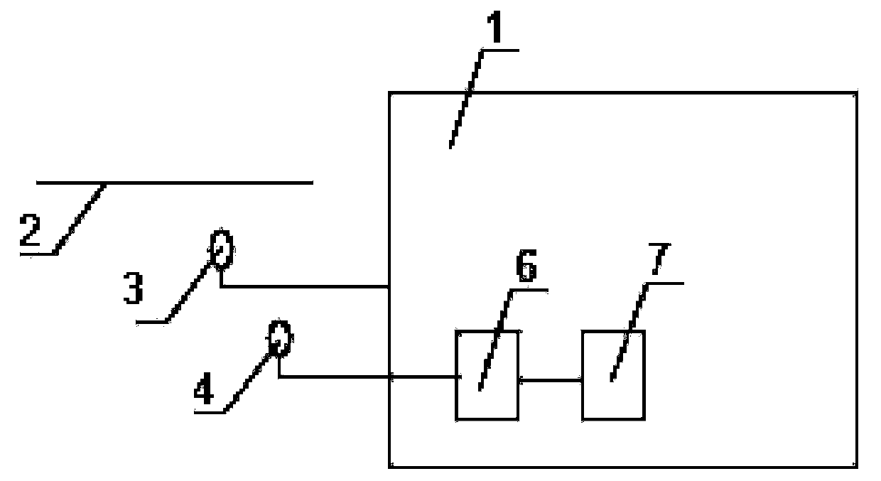
[0044] Such as Figures 1 to 3 As shown, this embodiment describes a printing recognition device based on infrared coding, which consists of a printing paper 2 with a color block 5 horizontally coated on the top of the back, an infrared light generator 3, an infrared detection device 4, a signal processing device 6 and a printing control device. The device 7 is composed.

[0045] The color block 5 printed on the printing paper 2 is a series of gray, white and black blocks with different gray scales. The color block 5 with 0% gray scale corresponds to the number 0, the color block 5 with 100% gray scale corresponds to the number 9, and the color with 50% gray scale Block 5 corresponds to the three values ​​of the number 5, and then use these three values ​​as anchors, according to the gray levels of other color blocks, they are defined as other numbers in 0-9 in turn, and these gray color blocks are arranged in a horizontal line without intermittent Row.

[0046] In this embo...

Embodiment 2

[0056] Such as Figure 4 , 5 As shown, this embodiment describes another printing identification device based on infrared codes, its structure is basically the same as that of Embodiment 1, of course, the printer 1 used in conjunction with it will be different, and what this embodiment uses is an upper cover 9 and 10 thermal printers under the cover. The difference is that, firstly, in this embodiment, the infrared light generator and the infrared detection device are combined to form a photoelectric pair 8, and the photoelectric pair 8 is installed as a component on the inner side of the printer; specifically, it is installed on the lower cover 10. Second, the color blocks 5 are printed on the back side of the printing paper 2 and the color blocks 5 are vertically arranged in a row. The positions of the photoelectric pair 8 and the color block 5 correspond to each other. When the printing paper 2 is running in the printer 1, the photoelectric pair 8 can detect the entire p...


PUM

PropertyMeasurementUnit
Widthaaaaaaaaaa

Abstract

The invention relates to a printing recognition device and coat-printing and data recognition method based on infrared coding. The printing recognition device and coat-printing and data recognition method are applied to a printer and printing paper. The recognition device comprises a recognition mark, an infrared generator and an infrared detection device, and the recognition mark is coated and printed on the printing paper. The infrared detection device is arranged in the printer. The recognition mark is coated and printed on the printing paper. The infrared detection device and the infraredgenerator are arranged in the printer. The recognition mark is composed of at least one set of color lumps with different gray levels and / or color differences, the adjacent color lumps with differentgray levels and / or color differences emit reflection light, and the infrared detection device is used for receiving the reflection light. Thus, the recognition aim is achieved. The printing recognition device and coat-printing and data recognition method have the advantages that the recognition effect is good, the cost is low, equipment is simple and effective, and preparing is simple.

Description

technical field [0001] The invention relates to an infrared coding printing recognition device and a printing and data recognition method, which are applied to printers and printing paper. Background technique [0002] Existing printer technologies have penetrated into all aspects of social life, especially in logistics and household applications, where printers are developing towards miniaturization and low cost. This also makes the printing equipment further popularized and applied. However, in office, study, and commercial printing equipment, especially when human body contact is required in people's life, work, and study, or as food packaging materials, it is necessary to ensure that the quality of the printing paper is stable or special technical means are required to ensure a good printing effect. For example, the lifespan of paper in the sun (ultraviolet rays), whether it is waterproof and oil-proof, whether it is sensitive to alcohol in the hospital environment, whe...

Claims


Application Information

Patent Timeline
IPC IPC(8): B41J29/393B41J11/00
CPCB41J11/009B41J11/0095B41J29/393
Inventor 李金辰李泰明
Owner 李泰明
Learn More